


Solutions
Effective Fault Codes with Accurate FRACAS Reporting are Dependent on Effective eXpress Diagnostics
Challenges Employing an Effective Failure Reporting and Corrective Action System (FRACAS)
When maintenance activities occur during the sustainment of a complex military asset, the ability
to perform maintenance and accurately report conclusions are an important requirement for cost effective sustainment. These activities are often complex and ineffective, inconclusive and costly due to the lack of diagnostic knowledge. This leads to the often experienced wasted time and cost and drives sustainment costs to unacceptable levels.
These sort of complex maintenance events typically begin from the asset or vehicle reporting a Failure Code that renders the asset unavailable until it can be repaired. But the association of Failure Codes to Fault Groups or Faulty LRU’s (Line Replaceable Units) is not always straight forward in the traditional field or depot maintenance environment(s).
The subject of this solution is focused on the ability to accurately report on failure indicators and the resulting maintenance actions.
It must be understood that one of the prime uses of FRACAS is to analyze Root Cause of actual failure for design improvement. This is not the diagnostics related failure analysis but the physical root cause. Failure could be from over load, excess heat, vibration of even manufacturing problems. This is more important in first few years of operation. Effective Reliability parameters are accrued from FRACAS reporting and data mining on more mature systems in the out years of operation to sort out the erratic failures. Figure 1, shows a typical FRACAS process flow.
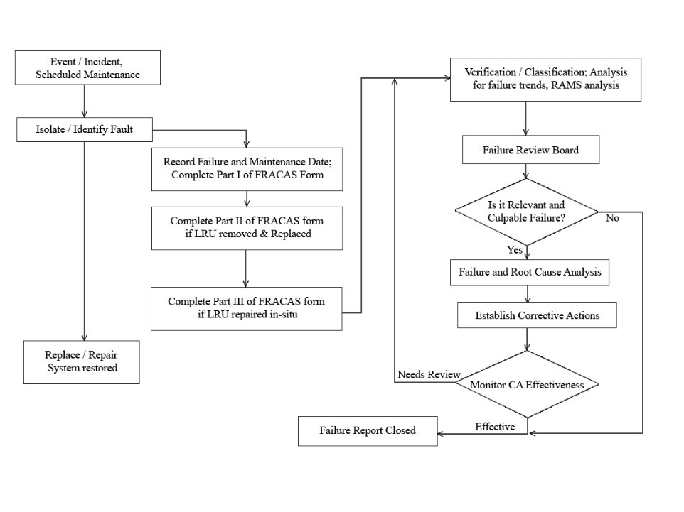
Figure 1, Typical FRACAS Process Flow
As shown in the FRACAS process, the very first action, the Identified failure event, falls apart if the failure reporting is not correct (bad Fault Code reporting). Then the Isolation to the failed replaceable unit is high risk without Diagnostics Knowledge. Then the recurring issue of No Fault Found (NFF) has a major impact on the FRACAS reporting. The point being made, an effective FRACAS process must be based on effective Diagnostics Knowledge of the system under test. This is accomplished through the eXpress Diagnostics Analysis process as an integral part of the Integrated Diagnostics Design process.
The other significant issue with the FRACAS process is the inconsistencies in interpreting the failure information and the accuracy of reporting the corrective action. This is where human error comes in. The more this process is automated, the more effective the results. This is explained later in this solution.
The Diagnostics Engineering tool eXpress with the ISDD approach is fully capable of establishing accurate and traceable “Fault Code to Fault Group” interrelationships in an exhaustive manner that can be synchronized with the Logistics Support Analysis (LSA / LSAR), and while enabling the diagnostics to key off Logistical Control Numbers (LCN) to ensure traceability throughout the Integrated Logistics Support paradigm. Other outdated approaches lack the comprehensive diagnostic discipline and knowledge required to integrate the Systems Engineering process and Sustainment effectively.
A “Lean” approach to the sustainment paradigm is interdependent with an effective design development process that can leverage the diagnostic acumen to ensure the fielding of a “smart lean” approach to reducing avoidable and any other interrelated costs throughout the sustainment lifecycle(s).
The inability to move between the diagnostic design and the diagnostic support activities in a seamless and interdependent manner, and other factors outside the diagnostic realm, impede the accuracy and comprehensiveness of solely relying of tracking and reporting failures.
Furthermore, the variable, program-independently-prescribed corrective actions to drive the FRACAS data for the data mining and computing of such metrics as MTBF, for example, can often evolve into the inadvertent reliance on the inaccuracies muddied into the collected sustainment data.
More meaningfully, we need to initially ensure component replacements were “required” to resolve complex system failure(s). Otherwise, FRACAS practices can mischaracterize failure resolutions as valid sustainment tactics. Worse yet, planning to use FRACAS as a primary driver to “mature” (at unpredictable costs) sustainment decision-making as a reactive-diagnostic approach to sustainment activities is not a solution that counter-balances inadequate sustainment decisions formed from the lack of achievement in securing sufficient knowledge of the inherent diagnostic design capability. Instead, FRACAS activities would be more serviceable in a supplemental sustainment advisory role.
When concerned about evaluating the decision-making utility of metrics derived from a “less-than-tight” recording of fielded failure and repair data, we suddenly become exposed to the relevance of effective integrated systems diagnostics design – like it or not. Fortunately, the Captured Integrated Systems’ Diagnostics Design discloses (and unambiguously identities) the interrelated component constituencies that are specifically involved in the playfield for determining the “integrated system-impact” of “failures” – any/all failures, loss of any functions or impending failures (in the event of deployment of CBM methodologies).
Such metrics that are formed from the accounting of deployed events, including, but not limited to, MTBF or MTTF, are, in part, characterized by the inherent diagnostic integrity of the Integrated Systems’ Diagnostics Design. Put another way, being in the position of “KNOWING” the diagnostic integrity of system design is a companion prerequisite for evaluating the decision-making utility of repair/replace sustainment metrics.
Questions to Ponder when Diagnostics are not a Serious Design Development Characteristic
What vetting process(s) was/were performed to ensure that the data obtained from (supervised or unsupervised, independent, etc.) sustainment events, which are used to seed System Level metrics (say, MTBF, MTTF, or any TTxx or MTBxx, etc.) are diagnostically-comprehensive and conclusive? Does the sustainment process enable a consistent means to ascertain when all failures were replaced, or alternatively is the process limited in its ability to identify failures not necessarily involved directly in the failure event(s) that triggered the sustainment activity? Put another way, did we replace all the failed components (considered during isolations that may have multiple independent failures) – including those that were not involved with the failure reported to spur the repair event?
Would the lack of sustainment consistency or thoroughness (and BTW, the order of testing will invoke a variance in failure constituencies) result in additional repair/replace events, thus being included in the data used to compute “time to” or “time between” failures or any availability-related metrics? If our inherent means to detect failures does not detect a failure (in any specific operational state), does that lack of diagnostic integrity positively increase the time between failure, or may it lead to additional “incipient” failures – skewing the data collected due to diagnostic inadequacies but reflected in frequency of ensuing repair/replacement anomalies? How will this impact data collected for “First Failures”, “time between first failures” or many other cousin metrics?
In the absence of knowing the Integrated-Systems Diagnostics Design, merely by happenstance, we invite back-end-driven costs into the unwitting reworking of sustainment decisions based upon conjecture of resolutions that may not be comprehensive, accurate and are too often, overly-presumptuous. For such reasons alone, FRACAS activities ought to target sustainment tweaking and tracking, and that will remain in its wheelhouse
Support Levels Typically Found in Maintenance/Sustainment Entities
Organizational Level Maintenance (O-Level)
Organizational (on equipment) level diagnostic capabilities commonly focus on how the system will detect and isolate faults to the LRU. Failures on an LRU may be detected and reported by an LRU level FD/FI controller. Depending on the specific component being monitored, the controller may reside on the local LRU (data processing module, for example), or it may be remote as in the case where pressure sensors monitor pump performance and provide information to a system controller diagnostic processing.
The subsystem level FD/FI controller monitors and integrates diagnostics within a subsystem or sub-segment, and the system level FD/FI controller monitors and integrates diagnostics across subsystems or segments on the product platform.
The system level FD/FI control function creates fault records that are transmitted to the support equipment personnel for intermediate level (I-level) maintenance actions
Intermediate Level Maintenance (I-Level)
Intermediate or Unit Level commonly addresses LRU repair which requires troubleshooting to the failed SRU. The ability for organizational field fault data be transitioned to the intermediate level (I-Level) will optimize LRU repair times, minimize RTOKs (retest okays) and provide traceability and trend data. Portable Maintenance Aid (PMA) may be implemented to evaluate fault data from the system, manages any necessary trouble-shooting, directs repair procedures, and maintains the system logbook. The PMA are typically designed to be used in the operational environment and intended to minimize transitions to intermediate level maintenance actions. Interactive Electronic Technical Manuals (IETMs) could be hosted within PMA and be fully integrated with the logbook, fault isolation, and other PMA functions.
Summary data from the PMA are transferred to the I-level computer system so field faults are traceable for I-Level troubleshooting and for historical data collection.
Depot Level Maintenance
Likewise, I-Level maintenance data can be utilized for depot level SRU repair. I-Level maintenance data transitioned to depot level facility can be a part of a larger information management system. Information regarding maintenance data can be linked between depot and suppliers/vendors.
A state-of-the-art diagnostic system architecture permits full integration of diagnostic functions from the LRU on and individual system platform, to fleet-wide maintenance activities. Contractor logistics support (CLS) program can ensure full integration of organizational and I-level diagnostics with the customer logistic systems.
Reuse the eXpress Diagnostic Design
For supportability, it would have been ideal if the diagnostic design for the fielded integrated system (end product) was captured in a form that was immediately transferable to the (evolving) sustainment paradigm. So, if we could continue to improve (evolve or “tweak”) the sustainment effectiveness based upon empirical data learned from prior diagnostic resolutions, we can actually produce an actual tracking (traceability to the delivered design at any point) of the sustainment resolutions over time.
As a sustainment activity is performed, it forever changes the failure characteristics of the fielded integrated system(s) and only diverges further throughout the remaining of the sustainment life-cycle.
This is just a very tiny hint at one of the hundreds of new capabilities we’d have in the sustainment life-cycle if we could fully capture the integrated systems’ diagnostic design integrity in the design life-cycle. We can also use a legacy system to “baseline” its inherent integrated diagnostic design capability. These may only appear as assessments initially, which is fine since most systems’ integrators could not tell us what the diagnostic integrity is for the inherent design of the fielded system.
When the diagnostic design is captured in a qualified model-based diagnostic engineering tool, one will “know” the inherent limits and constraints of the test coverage (sensors, test interference, etc.), and determine the impact on the detection and diagnostic isolation – Fully describe BIT or sensor coverage, sensor corroboration/or gaps per operational state or mission phase, etc. But the captured diagnostic design can also be fully mapped to the LORA or maintenance paradigm to discover if there is sufficient congruency with the diagnostic integrity (which will likely be a “first ever” experience for too many supportability or systems engineers. Going a tad further, one could also know the diagnostic capability of any “type” (subset) of diagnostic test – say BIT vs. BIT + 2nd level test (guided troubleshooting, etc.).
The following examples demonstrate how a diagnostic model can be used to “follow the breadcrumbs” that lead a maintainer through a model’s various levels of interpretation, such as in this case from Fault Code indexed Failure Modes through Failure Effects. That provides certainty in the trouble resolution.
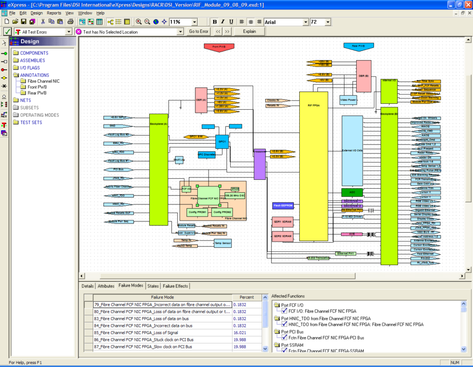
This first view shows the selected component (highlighted by the green squares) that includes its Failure Modes.
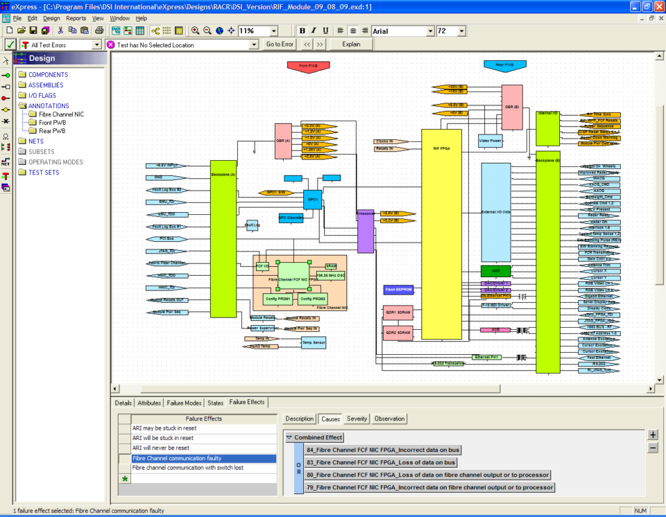
This view shows how the Failure Modes of the selected component are mapped to that component’s immediate Failure Effect.
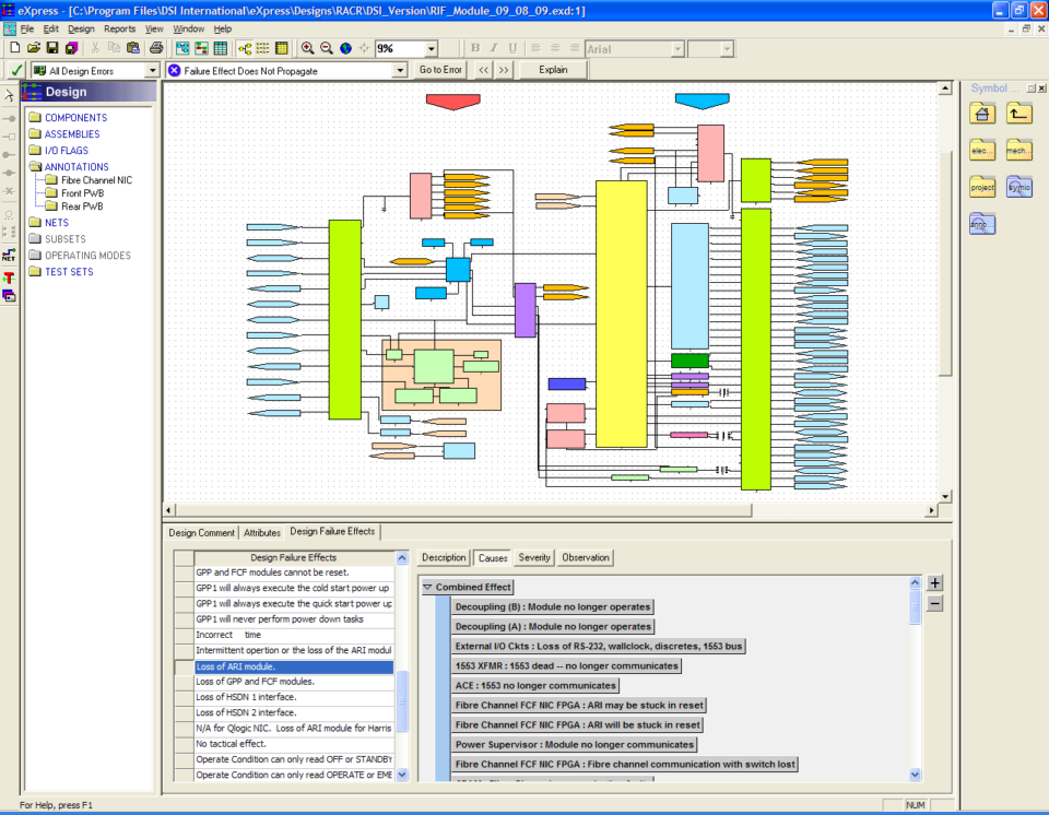
The final view shows how the component’s Failure Effect can, in turn, be mapped to the design’s Local Failure Effects.
Once captured, deliver the “design-based” diagnostics to the sustainment implementation solution(s) in an “agile” and scalable form to allow for “on-board” diagnostics and “back-end” troubleshooting diagnostics to be fully integrated with – not simple “test results” starting points, but rather “DIAGNOSTIC CONCLUSIONS” to begin the maintenance interrogation or activities.
Once the model design is completed, then it is possible to create a diagnostic study that can reference the Fault Codes and establish a diagnostic testing strategy.
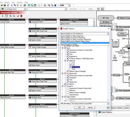
The diagram above show how information gathered in a model can be structured to provide a diagnostic testing strategy and even, as show in the diagram, export information to other compatible tools such as simulators or test executivesThis can be pushed into S1000D environments – but it will have a superior sequencing of the tests and far more accurate diagnostic conclusions. Then, any test resolutions can not only record “perceived” results, but rather record each diagnostic conclusion (what is suspected, exonerated or failed, etc.) for each diagnostic step based upon the artifacts of each sustainment session. This sort of “feedback” to the ensuing maintenance sessions ought NOT to be for course modifications to the diagnostic isolation methodology, but instead ought to serve as data to “tweak” or finely tune diagnostics. The tweaking only remains with the data, and whereas the captured integrated systems’ model remains intact to the design.
Remember, the method of using empirical data for influencing the maintenance activity (delivered in S1000D or any other required form) will frequently miss-isolate “first failures”. Contrarily, it is always a great feeling of confidence knowing that the captured integrated diagnostic design knowledge has captured these interrelationships (in an advanced model-based diagnostic engineering tool). But for complex integrated systems’ designs, a truly “agile” diagnostic approach will play to any (evolving or fixed) sustainment solution or maintenance “balance” (RCM, CBM, CM, etc.) by using BOTH design-based and history-based diagnostics to any desired level as determined by the system integrator of owner of the asset(s).
Related Links:
BIT Optimization – Validation – Integration
Integrate Test and Diagnostic Tools via ATML
Run-Time Authoring Tool
eXpress Design Viewer
DSI Workbench
History and Feedback Module
Related Videos:
Introduction to ISDD
BIT to Guided Troubleshooting
Diagnostic Validation
