


Solutions
Production Environment & ATE
Reuse the eXpress Diagnostic Design
Circuit Boards and Electronic designs are typically produced in various CAD-type tools rather quickly today. Tools, techniques and processes have greatly benefited the speed and quality of PCB or any CCA development effort, particularly in the Commercial Off-The-Shelf, or “COTS” environment.
Independent designers typically have limited specific knowledge of the functions or failure propagations that will be able to be assessed from the perspective of the operator of the fielded product. Since this sort of “fielded product” knowledge is not generally a responsibility of the independent Circuit Card or PCB designer, the responsibilities are instead reduced to assessing test coverage at the level of their specific independently-developed electronic design.
If the design was at first, influenced and optimized for diagnostic acumen rather than simply “Test Coverage” assessment data, we could gain significantly more value in the quality of design processes, its diagnostic effectiveness and the diagnostic integrity potential of the design piece prior to its possible reuse in any fielded product containing the design(s).
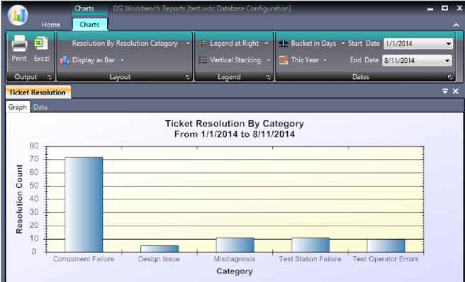
Beginning in DSI Workbench 3.5.0, the comprehensive Diagnostic Resolution Database interactively records the diagnostic conclusions and all diagnostic steps during the procedures, for Data Analytics to support the improving of the design, the test methodology or for improving future diagnostic sessions.
Diagnostic Design Interdependence
We have identified many techniques that design engineers use today to validate their “Test Coverage” at the level of their specific design piece, in and of itself. But is this design piece fielded, or is it a part of another fielded, “integrated system”? What is the design’s “Diagnostic” integrity? How do we assess the transferable portions of the design’s diagnostic capability? How can we improve or augment diagnostic process into our design to enrich the feedback of the diagnostic integrity to the design development activities in time to benefit both product manufacturing and also future fielded support activities?
The knowledge of a design’s diagnostic integrity will not only help improve quality of the design, but the strengths and weaknesses of the manufacturing processes will also be discovered. But the value doesn’t end in manufacturing, when the design is captured in eXpress, the value of the eXpress knowledgebase will keep returning dividends throughout the lifecycle of the design itself, and the fielded product to which it ultimately resides.
Even the most popular and capable CAD tools have limited diagnostic capability. Those that have paid some recent attention to the need for DFT or any diagnostic capability for the design still are limited to the digital or electronic design domain. We all should realize that this is a good start, but is totally inadequate, and could prove to be a vacuous endeavor once the design is integrated into the complex integrated, or “fielded” system. At this point is where the higher system-level diagnostics may be grossly unable to positively and uniquely indict this lower-level design piece that appeared to be a diagnostic design dream at the level of the design piece – by itself. As a result, the fielded product still remains unavailable.
Recognizing Diagnostic Design Hierachy as a key Requirement for “Integrated” Diagnostic Accumen
Every design piece, regardless of design domain origin, that comprises the operational or fielded integrated system can be included in the eXpress diagnostic modeling paradigm. COTS, GFE or Proprietary components can be included in any eXpress System Model and in a manner that is sensative to any design specific design properties or proprieties. The eXpress System Model will always present the system’s overall diagnostic capability in the terms of how it actually exists at any level, any separation or mixture of suppliers or subsystems, or at the comprehensiveness of the design in the sustainment environment(s).
The Electronic Control Unit (ECU) of a ABS Braking System Example
Since the better way to understand the value of upgrading DFT to Design for Diagnosability, or DFD, is to walk through a few screen captures to depict a little of the process, but also to present how a quality Diagnostic Design Integration process would be easy implemented.
The eXpress diagnostic model can represent any diagnostic design level, so focusing in on just the Electronic Control Unit of an automobile’s Automatic Braking System (ABS) will allow us to use see how DFT can be made much more diagnostically capable. The eXpress model is an ideal place to capture the diagnostic design since it can not only perform all of the Testability and advanced diagnostic assessments, but it can “push” the diagnostics for gametime play – in the lab, field or anywhere or anytime diagnostics are demanded.
Using the Diagnostic eXpress model to Enrich DFT
The series of images below depict our generic example of the ABS system of an automobile. The eXpress model was built to represent all of the diagnostic characteristics of the design since it has captured all of the design’s functional and failure interdependencies in a unique and comprehensive form.
Since eXpress is highly interoperable with most any data form, particularly with data stored in a spreadsheet, extensive design or component properties can usually be easily imported. Some data forms, like component Failure Rates, or MTBF from Reliability Engineering activities may already be available, and can be imported into the eXpress model for assessment objectives since it will be used in any needed Fault Isolation calculations, etc. Eventually, this data will be considered in the enriching of sustainment actions as well.
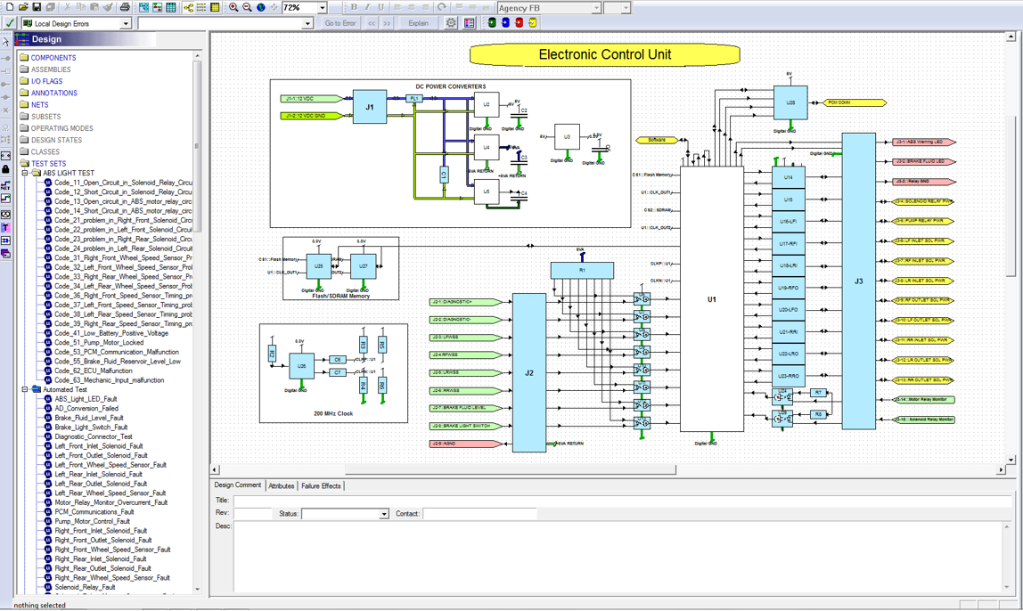
The eXpress model above shows the ECU in the main design window along with the entire listing of “Tests” on the left in an “Explorer Tree” form, that represent every available testing node in the design (on the circuit board). The eXpress model is a representation of the design in terms of the functional or failures propagate through the design through the specific “input” or “output” ports on each object that is connected to other objects by “nets” that depict the “functional flow” through the design(s).
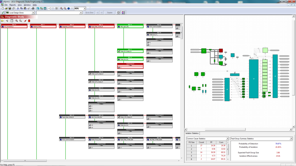
The image above depicts eXpress’ “diagnostic tree” in the left window and the diagnostic impact on the design in the right window. Traversing the diagnostic tree down on the far left column will reveal all of the design’s “Fault Detection” tests. Traversing the diagnostic tree to the right and then downward will reveal the diagnostic sequencing required to “Fault Isolate” to any failure or its “Fault Group”, or “FG.
The image above also shows the diagnostic integrity of the design in the lower right window, where the Probability of Fault Detection and Fault Isolation are described for any Fault Group, “FG” size.
Exporting the eXpress diagnostic Model via DiagML
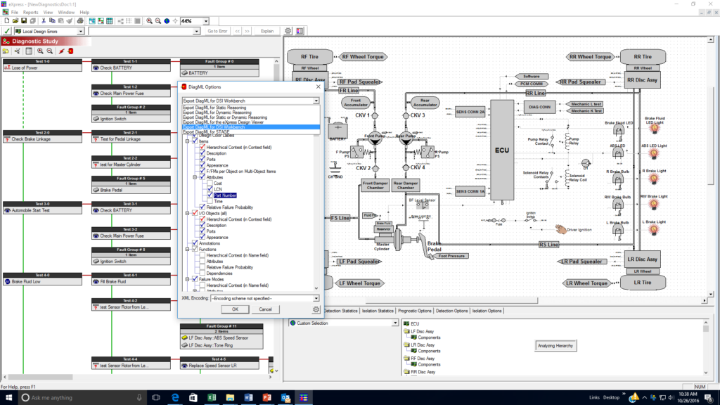
After the eXpress design has been cleared of errors and has been validated by the eXpress diagnostic validation capability using the Desktop Fault Insertion, or “DFI” feature, the diagnostic integrity of the ABS design will be finalized and then the model is exported through the eXpress DiagML export mechanism. The DiagML export capability in eXpress has intelligent default settings that often eliminate any further customization of the exported file for lab or field diagnostic usage.
In the image below, the diagnostics are able to be easily exported from eXpress by using the DiagML export (“red data base can” icon) option in the any of its “Diagnostic Studies”. The DiagML export capability facilitates a wide variety of uses for the diagnostics created in eXpress, which is evidenced by a careful looking at the various packaged configurations appearing in its “drop-down” dialog.
Pulling the exported Model into “RTAT” and DSI Workbench
The “Run-Time Authoring Tool”, or RTAT, is a flexible tool that allows diagnsotic procedures exported from eXpress to be enhanced with graphic overlays and links to external documents. Diagnostics can also be reformatted for use in a variety of popular Production ATE tools directly or through DSI Workbench.
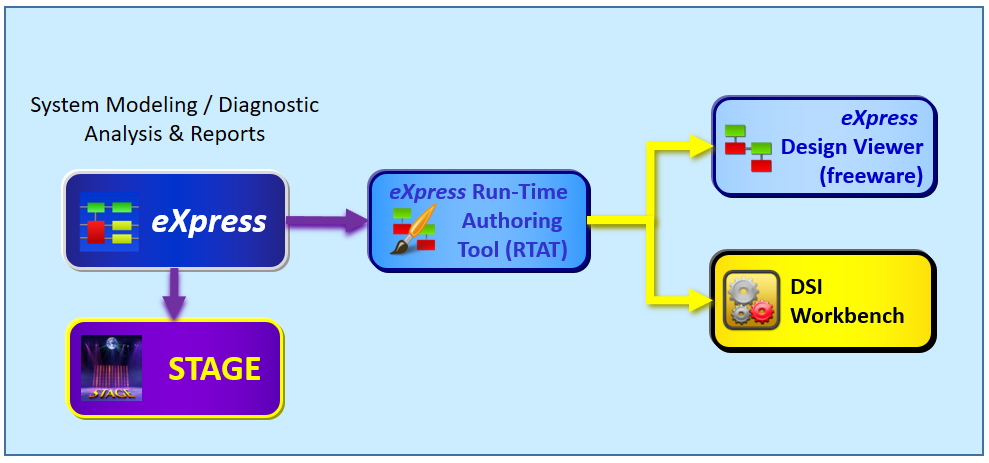
DSI Workbench allows diagnostics to be fielded in a maintenance or production environment. Because DSI Workbench serves as a diagnostic Reasoner, one of its uses is in concert with any ATE or ATS solution(s).
Through a highly customizable GUI, that can be easily tailored for the most lavish sustainment objectives in RTAT, DSI Workbench can perform hand-in-hand as a Diagnostic Reasoner with the ATE.
As the ATE provides the “pass” or “fail” Test Results through the DSI Workbench Reasoner (using PDEL or ATML data exchange schemas) the test results are associated to the diagnostic design from eXpress. As DSI Workbench retrieves the test results from the ATE while in its’ “Monitoring Mode”, it is able to very simply correlate the test results interactively against the design’s captured expert diagnostic knowledgebase.
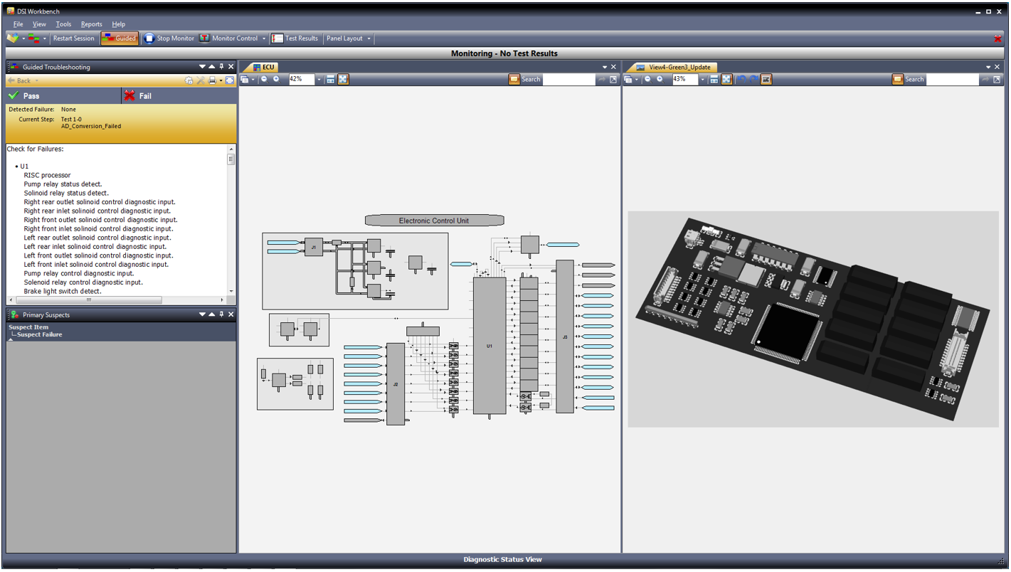
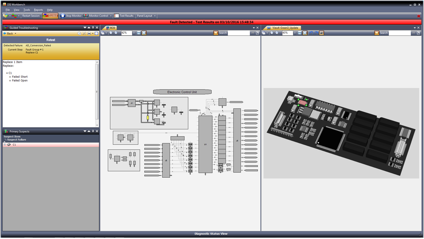
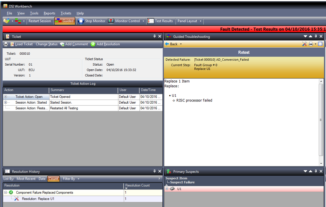
When a failed test is discovered and reported from the ATE, DSI Workbench will instantly indict the failed component(s) along with any other secondary suspected failed component(s). If the diagnostic integrity of the design is not able to allow a single component to be indicted, then DSI Workbench will provide an immediate status of all of the possible primary and secondary suspects to its GUI. This is a vivid capability that can be extremely explicit so that the technician can now enter the Guided Troubleshooting mode of DSI Workbench to perform the final steps of the Fault Isolation procedure, but while being guided by unmatched guidance and diagnostic accuracy.
Pulling the exported Model into ATML Pad
After the eXpress Model is exported from eXpress using DiagML (freeware available for public use: an XML schema representing the diagnostic properties and other related characteristics) it is immediately imported into “ATML Pad”, for translation into the desired ATML context. ATML, “Automatic Test Markup Language” is an industry-sponsored representation of sets of schemas that target a broader use of transferring any testing data or information.
The image below depicts the GUI from ATML Pad (by Reston Software) that has been keenly designed to fully accept the eXpress diagnostics as provided within a DiagML file.
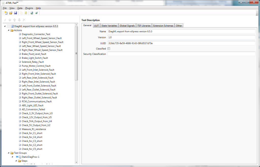
Once the diagnostic design is in ATML Pad, many other highly interoperable capabilities take on life!
| Seven Simple Steps to Enhance DFT with Diagnosability Acumen using COTS Tools | ||
| 1 | eXpress | Capture Diagnostic Design in the eXpress Diagnostic Engineering Tool |
| 2 | DiagML | Export Diagnostic Design from eXpress |
| 3 | RTAT | Import Diagnostic Design into RTAT |
| 4 | ATMLPad | Import Diagnostic Design into ATMLPad Data Translation Tool |
| 5 | ATE | Executes “Tests” and reports “Pass” or “Fail” “Test Results” |
| 6 | DSI Workbench | Used as an interactive Diagnostic Reasoner until a Failed Test is reported |
| 7 | DSI Workbench | Used as an expert interactive diagnostic Reasoner in Guided Troubleshooting |
The next three images below depict how any capable and popular ATE would be integrated with DSI Workbench to add the diagnostic expertise to its native capability of executing tests and retrieving test results.
Image 1: Popular ATE
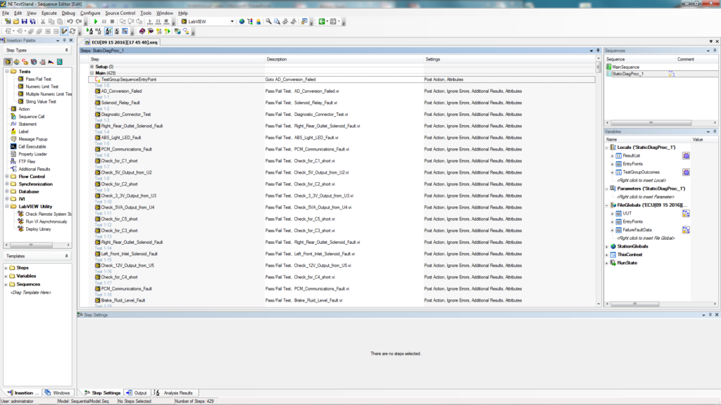
Image 2: “PASSED” Test Results:
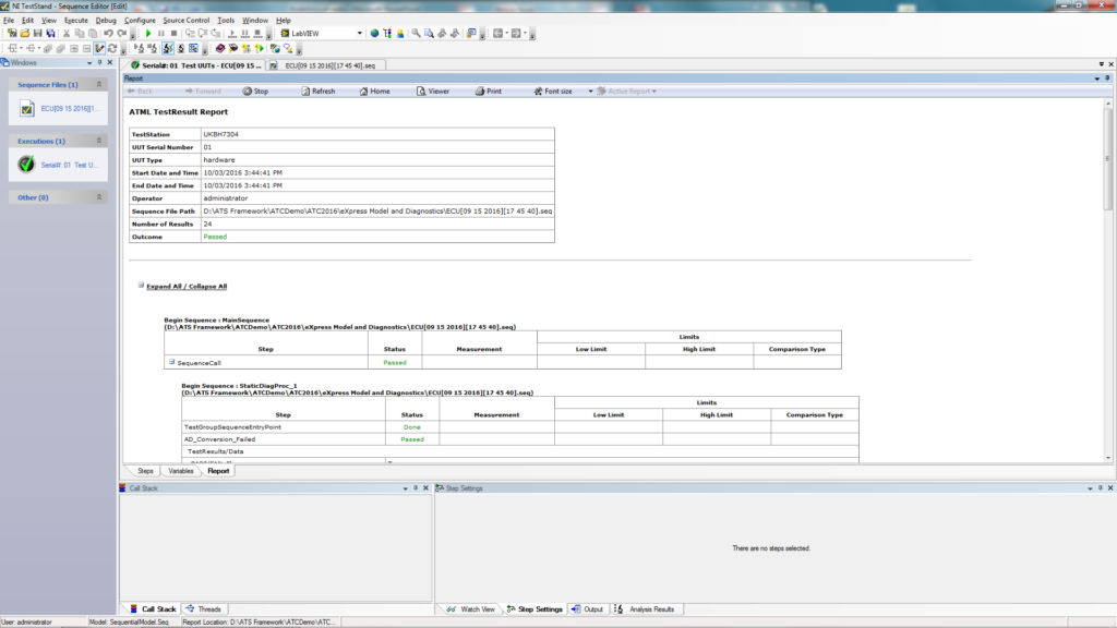
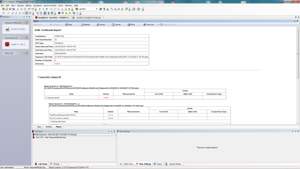
Image 3: “FAILED” Test Results:
DSI Workbench can present any useful test or repair documentation to the technician. Highly graphic videos and extensive images can be used to visually point out the failed and suspected components. A quick right click on the component will invoke a “Properties” dialog to display that identifies every possible characteristic about the component along with links to full test or repair documentation.
While this solution adds the diagnostic acumen directly to the Production lab ATE, this captured design knowledge can be further integrated with other designs as this design is included in any other fielded product or Integrated System(s).
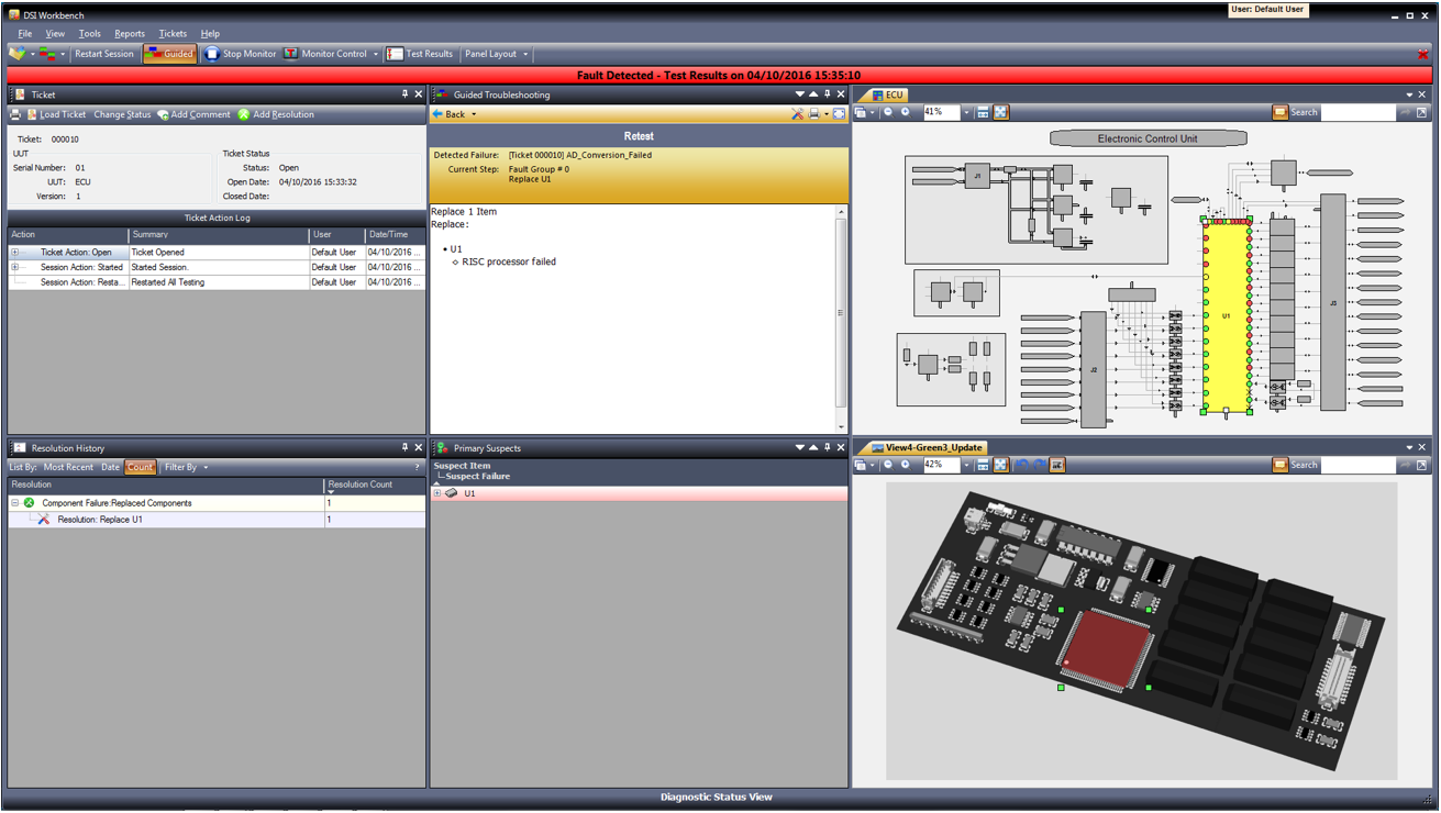
The image below provide a closer look at some areas of a few of the possible dialogs available within the advanced GUI of DSI Workbench. Incidentally, the Diagnostic Session “Ticket” capability enables a full tracking of any failures identified and fully isolated along with the full diagnostic path towards the indicting of the failure(s). This is a tremendous benefit for tracking design or process flaws during the production or occurring during a certain point in time after the design has been fielded.
Related links
BIT Optimization and Implementation
Integrate Test and Diagnostic Tools via ATML
Run-Time Authoring Tool
eXpress Design Viewer
DSI Workbench
History & Feedback Module
Related Videos
Introduction to ISDD
BIT to Guided Troubleshooting
Diagnostic Validation
COTS-Based Solution for Through-Life Support
