


Solutions
Deploying Diagnostics and Leveraging Empirical Data
Design Influence for Ensuring Decision-Making Data Quality
Most every traditional diagnostic approach is constrained by being based on the unintegrated-with-design use of diagnostic design data – or by a test-to-failure probabilistic approach. Both approaches rely upon the algorithmic association of non-design-integrated design data and/or the non-design-integrated fielded data, to the assumed faults based upon an acceptable level of certainty from uncertain test coverages. These are both data-driven approaches to establishing a diagnostic capability. Unfortunately, neither are formed from an integrated approach that leverages the depth and breadth of the design development process, nor in a manner that can fully associate the data retrieved during the integrated support activities against the diagnostic integrity of the fielded design.
Designed-Based Diagnostics
Design-Based Diagnostics can represent the independent diagnostic capability of each piece of the design. It will consider any diagnostic constraints, including the test coverage, of that specific design independently, or pseudo-dependently of “system-associated” designs. It is not able to fully consider the diagnostic impact as may be caused by the integration with any other design (Test Coverage constraints) and/or within any operational environment(s). That said, however, the diagnostic integrity of the design can be fully identified or validated in the eXpress modeling application.
History-Based, or “Case-Based” Diagnostics
History, or “Case-Based” Diagnostics are not based on the diagnostic capability of the design, but rather they are typically initially based upon general “test-to-fault” association as may be identified at the conclusion of the design development process. This data is then used to seed a data collection method that will be implemented at or during the operation and supporting of the fielded design. As the design is maintained, the resolutions retrieved from the corrective action rendered is collected in a database and continues to be augmented by the adding of additional corrective actions rendered to solve similar or other repair activities that appear to resolve the failure. Using the “history” of stored corrective actions to bias or influence future corrective actions is a sort of heuristic approach based upon, or reasoned from, similar “cases”. In this manner these approaches use “empirical data” (as opposed to “knowledge) to attempt to improve future diagnostic activities.
Empirical Diagnostics
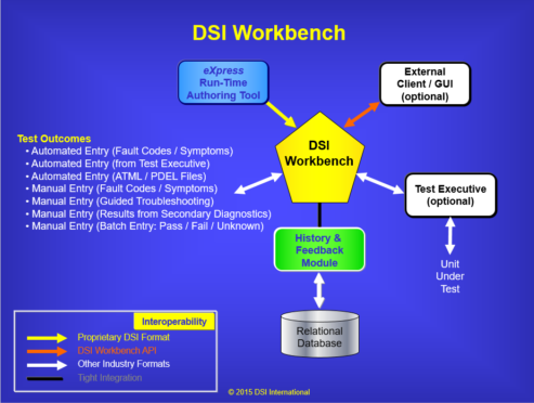
Empirical Diagnostics infer that the current operational diagnostics implemented, employ the weighted strategic use of relevant historical data resulting from the apparent successful corrective actions previously performed. DSI Workbench contains an optional “History and Feedback” and an interrelated database that can fully exploit this form of Diagnostics.
Web Based Diagnostics
For those less sensitive systems, the diagnostic paradigm can include the option to include web based diagnostics. DSI Workbench can be used in a remote environment that ties into a centralized database using web based services In this capacity, DSI Workbench can operate as a client devise that can send and retrieve test or repair information while logged into a centralized database using the optional database DSI Workbench Data Administrator Module. In this implementation, web based Diagnostics can be tracked and all diagnostic resolutions can be used to enhance future test sequencing for the next diagnostic session on the individual application, or may also be used to update the test sequencing across a broader scope or fleet, when desired.
For more advanced Health Management to off-board troubleshooting environments, web based diagnostics can be used to provide BIT code status to field operations enabling enhanced informed-maintenance tactics to be initiated. Of course, private or secure networks can also be used for similar objectives while maintaining full and comprehensive diagnostic prowess.
“Integrated Systems Diagnostic Design-Based” (ISDD) Diagnostics
Unique to ISDD, it is formed as an integrated approach throughout the design development process and can fully accommodate the evolving or changing design, including design or technology updates, and alternative sustainment approaches throughout the sustainment lifecycle(s). ISDD-Based Diagnostics can fully represent the diagnostic capability of the design – as it exists now, or whenever “now” can infer. It considers any diagnostic constraints as is reflected in any independent design and/or with any constraints imposed by the integration of any other designs, including “Test Coverage” constraints and its operational environment(s). Since the diagnostic integrity of the design can be fully identified in the eXpress modeling application. It is also able to be augmented with Empirical Diagnostics to further support effective sustainment approaches, but without losing the traceability back to the design at all time.
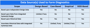
The “Data Source(s) Used to Form Diagnostics” chart above, summarizes four (4) approaches to seed the diagnostic capabilities. Understanding the strengths and weaknesses of the diagnostic capability of the design can better prepare the forming of any design or sustainment decisions that are constrained by the diagnostic integrity of our design.
Reuse the eXpress Diagnostic Design
For supportability, it would have been ideal if the diagnostic design for the fielded integrated system (end product) was captured in a form that was immediately transferable to the (evolving) sustainment paradigm. So, if we could continue to improve (evolve or “tweak”) the sustainment effectiveness based upon empirical data learned from prior diagnostic resolutions, we can actually produce an actual tracking (traceability to the delivered design at any point) of the sustainment resolutions over time.
When the diagnostic design is captured in eXpress, we will “know” the inherent limits and constraints of the test coverage (sensors, test interference, etc.), as this is a core competency of eXpress. As such, this enables a much more accurate and conclusive association between Fault Codes and Fault Groups, which is not a stronger characteristic of most any traditional approach involving the on-vehicle to off-vehicle bridging of the “Fault Codes to Fault Groups” association. With eXpress, the second level isolation can be seen in the diagnostic tree during design development, ensuring that the path towards accurate “next level” diagnostic sessions is fully retained
In the images below, notice that the on-board BIT may have only the (test coverage) ability to report the diagnostic status up until “Test 1-1”, at which point any further diagnostic isolation (moving to the right) is to be performed in the off-board, or “Second Level” Diagnostic Session. This second level will be cognizant of the entire set of on-board BIT inferences from a diagnostic conclusive standpoint, enabling continued Guided Troubleshooting or ATE to be fully armed with this comprehensive diagnostic knowledge as it is carried forth into this second level diagnostic session:
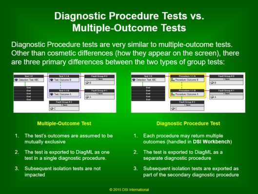
The image above shows how eXpress is able to seamlessly transition between the “Multiple-Outcome Tests” and establish the “Diagnostic Procedure Tests” in creating full diagnostic continuity between the diagnostic conclusions obtained from on-board BIT and the off-board ATE or Guided Troubleshooting environments.
Exporting the eXpress diagnostic Model via DiagML
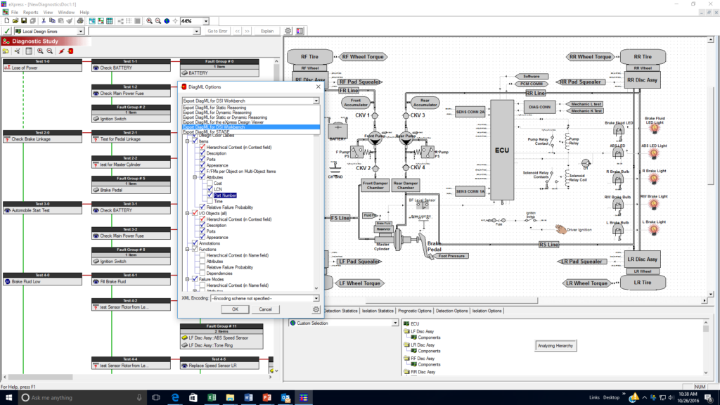
After the eXpress design has been cleared of errors and has been validated by the eXpress diagnostic validation capability using the Desktop Fault Insertion, or “DFI” feature, the diagnostic integrity of the any design will be finalized and then the model is exported through the eXpress DiagML export mechanism. The DiagML export capability in eXpress has intelligent default settings that often eliminate any further customization for field diagnostic usage.
In the image below, the diagnostics are able to be easily exported from eXpress by using the DiagML export (“red data base can” icon) option in the any of its “Diagnostic Studies”. The DiagML export capability facilitates a wide variety of uses for the diagnostics created in eXpress, which is evidenced by a careful looking at the various packaged configurations appearing in its “drop-down” dialog.
Pulling the exported Model into “RTAT” and DSI Workbench
The “Run-Time Authoring Tool”, or RTAT, is a flexible tool that allows diagnsotic procedures exported from eXpress to be enhanced with graphic overlays and links to external documents. Diagnostics can also be reformatted for use in a variety of popular Production ATE tools directly or through DSI Workbench.
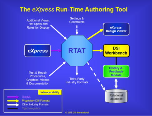
DSI Workbench allows diagnostics to be fielded in a maintenance or production environment. Because DSI Workbench serves as a diagnostic Reasoner, one of its uses is in concert with any capable or popular ATE in the production environment.
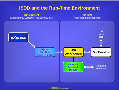
The charts above and below describe the primary tools at their respective purposes within the ISDD environment.
Retaining Captured Expert Knowledge
Once captured, in this ISDD environment, delivering the “design-based” diagnostics to the sustainment implementation solution(s) in an “agile” and scalable form to allow for “on-board” diagnostics & “back-end” troubleshooting diagnostics is a scalable and seamless endeavor.
The unique advantage to using ISDD to influence design development is that the fielded diagnostic and sustainment activities can be fully integrated with – not simple “test results” starting points, but rather “DIAGNOSTIC CONCLUSIONS” to begin the maintenance interrogation or activities. This can be pushed into S1000D environments – but it will have a superior sequencing of the tests and far more accurate diagnostic conclusions. Then, any test resolutions can not only record “perceived” results, but rather record each diagnostic conclusion (what is suspected, exonerated or failed, etc.) for each diagnostic step based upon the artifacts of each sustainment session. This sort of “feedback” to the ensuing maintenance sessions ought NOT to be for course modifications to the diagnostic isolation methodology, but instead ought to serve as data to “tweak” or finely tune diagnostics. The tweaking only remains with the data, and whereas the captured integrated systems’ model remains in tack to the design.
Combining Captured Design Knowledge with Empirical Data
Remember, the method of using empirical data for influencing the maintenance activity (delivered in S1000D or any other required form) will frequently mis-isolate “first failures”. Contrarily, it is always a great feeling of confidence knowing that the captured integrated diagnostic design knowledge has captured these interrelationships (in an advanced model-based diagnostic engineering tool). But for complex integrated systems’ designs, a truly “agile” diagnostic approach will play to any (evolving or fixed) sustainment solution or maintenance “balance” (RCM, CBM, CM, etc.) by using BOTH design-based and history-based diagnostics to any desired level as determined by the system integrator of owner of the asset(s).
This is just a very tiny hint at one of the hundreds of new capabilities we’d have in the sustainment life-cycle if we could fully capture the integrated systems’ diagnostic design integrity in the design life-cycle. We can also use a legacy system to “baseline” its inherent integrated diagnostic design capability. These may only appear as assessments initially, which is fine since most systems’ integrators could not tell us what the diagnostic integrity is for the inherent design of the fielded system.
Independent designers typically have limited specific knowledge of the functions or failure propagations that will be able to be assessed from the perspective of the operator of the fielded product. Since this sort of “fielded product” knowledge is not generally a responsibility of the independent Circuit Card or PCB designer, the responsibilities are instead reduced to assessing test coverage at the level of their specific independently-developed electronic design.
If the design was at first, influenced and optimized for diagnostic acumen rather than simply “Test Coverage” assessment data, we could gain significantly more value in the quality of design processes, its diagnostic effectiveness and the diagnostic integrity potential of the design piece prior to its possible reuse in any fielded product containing the design(s).
As a sustainment activity is performed, it forever changes the failure characteristics of the fielded integrated system(s) and only diverges further throughout the remaining of the sustainment life-cycle. This is the purpose of absorbing trends discovered by the partnering of Empirical diagnostics with Design-Based Diagnostics.
Recognizing Diagnostic Design Hierachy as a key Requirement for “Integrated” Diagnostic Accumen
Every design piece, regardless of design domain origin, that comprises the operational or fielded integrated system can be included in the eXpress diagnostic modeling paradigm. COTS, GFE or Proprietary components can be included in any eXpress System Model and in a manner that is sensitive to any design specific design properties or proprieties. The eXpress System Model will always present the system’s overall diagnostic capability in the terms of how it actually exists at any level, any separation or mixture of suppliers or subsystems, or at the comprehensiveness of the design in the sustainment environment(s).
DSI Workbench and Building an Empirical Database
Through a highly customizable GUI, that can be easily tailored for the most lavish sustainment objectives in RTAT, DSI Workbench can perform hand-in-hand as a Diagnostic Reasoner with the ATE.
Database Management
Within DSI Workbench the Database Management Tool can be accessed from the database menu by selecting “Project Database” from the database menu. The database may only be managed from the project menu. Within DSI Workbench and administrator may create a database, select a project to use the database and then add the project to the database. The database management tool will allow the user to add users, configure user rights and setup system tables.
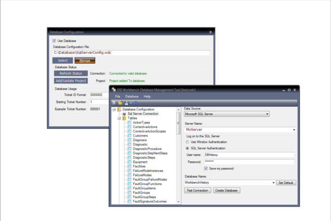
DSI Workbench Database History and feedback be tracked through the DSI Workbench database module. The setup and configuration of the database can be performed in either the Run-Time Authoring Tool or directly within DSI Workbench using and administrator login.
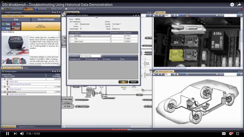
When a failed test is discovered and reported from the ATE, DSI Workbench will instantly indict the failed component(s) along with any other secondary suspected failed component(s). If the diagnostic integrity of the design is not able to allow a single component to be indicted, then DSI Workbench will provide an immediate status of all of the possible primary and secondary suspects to its GUI. This is a vivid capability that can be extremely explicit so that the technician can now enter the Guided Troubleshooting mode of DSI Workbench to perform the final steps of the Fault Isolation procedure, but while being guided by unmatched guidance and diagnostic accuracy.
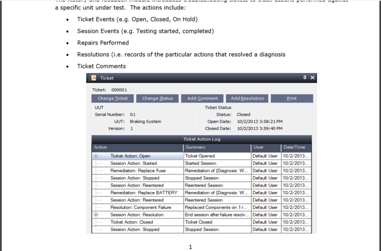
Troubleshooting Tickets
Within DSI Workbench, the “History and Feedback Module” introduces troubleshooting tickets to track actions performed against a specific unit under test.
The actions include:
- Ticket Events (e.g. Open, Closed, On Hold)
- Session Events (e.g. Testing started, completed)
- Repairs Performed
- Resolutions (i.e. records of the particular actions that resolved a diagnosis
- Ticket Comments
Resolution History
A resolution history panel provides the user with details of prior resolutions of faults (i.e. resolutions are the specific repairs performed that resolved the diagnosis). Resolutions can be displayed by the resolution date or by the number of times a resolution occurred within the selected date range.
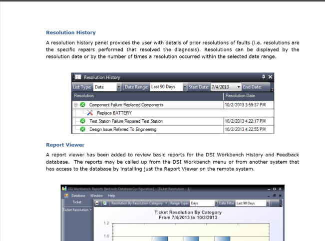
Report Viewer
A report viewer has been added to review basic reports for the DSI Workbench History and Feedback database. The reports may be called up from the DSI Workbench menu or from another system that has access to the database by installing just the Report Viewer on the remote system.
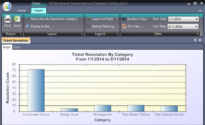
Beginning in DSI Workbench 3.5.0, the comprehensive Diagnostic Resolution Database interactively records the diagnostic conclusions and all diagnostic steps during the procedures, for Data Analytics to support the improving of the design, the test methodology or for improving future diagnostic sessions.
| Five Simple Steps to Leveraging Empirical Data for Diagnostics | ||
|---|---|---|
| 1 | eXpress | Capture Diagnostic Design in the eXpress Diagnostic Engineering Tool |
| 2 | DiagML | Export Diagnostic Design from eXpress |
| 3 | RTAT | Import Diagnostic Design into RTAT |
| 4 | DSI Workbench | Used as an expert interactive diagnostic Reasoner in Guided Troubleshooting |
| 5 | History & Feedback | Used to Record, Track and Influence ensuing Test and Diagnostic Sessions |
DSI Workbench can present any useful test or repair documentation to the technician. Highly graphic videos and extensive images can be used to visually point out the failed and suspected components. A quick right click on the component will invoke a “Properties” dialog to display that identifies every possible characteristic about the component along with links to full test or repair documentation. While this solution adds the diagnostic acumen directly to the Production lab ATE, this captured design knowledge can be further integrated with other designs as this design is included in any other fielded product or Integrated System(s).
Related links
BIT Optimization and Implementation
Integrate Test and Diagnostic Tools via ATML
Run-Time Authoring Tool
eXpress Design Viewer
DSI Workbench
History & Feedback Module
Related Videos
Introduction to ISDD
BIT to Guided Troubleshooting
Diagnostic Validation
COTS-Based Solution for Through-Life Support
