


Solutions
Calculation of Standard Testability Metrics
Calculation of Standard Metrics for Defense/Aerospace
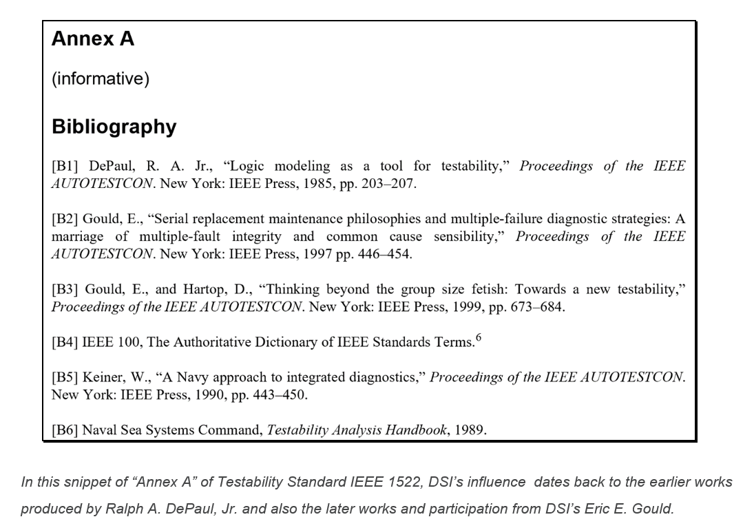
Since DSI is the original pioneer of the need for Testability as an integral component of the design development process for the US Department of Defense, and has mentored William Keiner, author of the first Testability Standard (MIL-STD 2165) prior to its acceptance in 1986, we have continued to lead industry in this purpose.

Testability Standards MIL-STD 2165 and IEEE 1522
In 1989, just a few years after the release of MIL-STD 2165 (1986), DoD and industry conferred to work on a more comprehensive capability, part of which initially revolved around “Testability”, by introducing “AI-ESTATE” (Intelligence Exchange and Service Tie to All Test Environments: IEEE1232). This new IEEE Testability Standard was going to eventually be identified as IEEE1522. The need for this new standard was a look at the future of what was possible to achieve through “Testability” (later identified and distinguished as “Diagnosability” in IEEE1522). The document will describe the branching of the term, “Testability” into the forming of two (2) tangential paths described as Testability and Diagnosability. The difference being that Diagnosability would also include and require calculations for “Fault Isolation” in conforming with a minimum set of standard design assessment metrics.
Additionally, a serious Testability analysis will underscore the vast differences between “test” (detection) and “diagnostics” (fault isolation).
One of the core objectives of Testability Standard IEEE 1522 was to enable the open interchange of diagnostic data between design and support tools and technologies. The objective assumed that if the Fault Isolation characteristics and metrics were universal, then a program could swap in diagnostic or test tools that could equally interpret the format used to exchange the diagnostic sequencing data. This format would give rise to new interchange prospects by that would eventually use ATML. DSI had preceded IEEE’s push to support ATML, with its own open XML diagnostic interchange format, “DiagML”. But while DSI’s ISDD Tool Suite uses the broader diagnostic capability of DiagML, ISDD also supports the most popular and advanced diagnostic uses of ATML.
DSI had preceded IEEE’s push to support ATML, with its own open XML diagnostic interchange format, “DiagML”. But while DSI’s ISDD Tool Suite uses the broader diagnostic capability of DiagML, ISDD also supports the most popular and advanced diagnostic uses of ATML when Integrating Test and Diagnostic Tools via ATML.
Testability Analysis that Lives beyond Design Development
While complex board level designs have been benefiting from using eXpress Diagnostic Engineering tool over the years, the primary value area has been on the application of System Testability as a method to influence the complex or critical design for sustainment over the lifecycle of the product. As such, DSI has had to transcend the purpose of Designing for Testability beyond the simple generation of Fault Detection (FD) and Fault Isolation (FI) metrics, and into a full systems’ integration process that seeds the design and support disciplines with unparalleled and continued value.
Why stop at generating the (FD/FI) numbers when you can export the diagnostic data through a one-button push to a Diagnostically-savvy XML schema, or “DiagML”? Or, publish the operational run-time diagnostic “Test Sequencing” into DSI Workbench to open up a vast new data interchange capability with ATML or IEEE S1000-D? The value of reuse of any investment made during design development is certainly a tremendous value, but to reuse this investment over and over again, for many purposes or yet evolving purposes, is another tremendous leap in value.
Testability – Variance in Goals
With ISDD, the Testability analysis does not solely target ineffective “one-&-done” goals. Unfortunately, the “one-&-done” get the “checkbox checked” goal has been ubiquitous in too many areas where customers and contractors alike dismiss the value and opportunity that diligent Testability Analysis will absolutely produce.
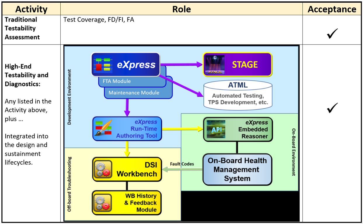
ISDD is DSI’s process that avails the use of many “back-end” tools for use in a myriad of seamlessly integrated production and sustainment activities. DSI’s high-end eXpress tool enables the capturing and analyzing of the design and provides unmatched facilities to perform and service every type of diagnostic application imaginable – and beyond. But that’s for you to discover throughout this website.
“Testability” Confusion
Many programs have “Testability Requirements”, which are, today, a bit confusing. In attempting to sort out some of the confusion, when we discuss eXpress, in the context of this website, we are primarily referring to the ability to test, detect and/or isolate faults on both low complexity designs as well as for very large, critical or complex fielded assets. This will help keep us on track when those performing a Testability analysis (with or without a “Testability Software Tool”) outside the context of eXpress, are largely referring to performing an analysis, which essentially limits Testability to reporting on the ability to “detect” or “isolate” faults at the component, CCA (circuit board), or sometimes even the (digital) sub-assembly level(s).
Immediately, we should notice the primary use of eXpress is to consider all integrated subsystems, which often includes every design that any other lower-level Testability analysis may include, but with the intention on bringing all of the lower-level analyses to the operational or deployed asset system level. Reporting on the Testability analysis at every integrated level of the deployed asset level is not typically comprehensively performed without the use of a robust tool that targets these requirements. This is a basic qualifier, but remains as an initial strong suit of eXpress.
But this initial discrepancy in the targeting of the application of Testability is just the beginning of the confusion of the embracing of Testability.
Introducing “Design For Test” or “DFT”
Much of the confusion originates in discussions where circuit board designers are discussing specific techniques to ensure that their circuit board is testable by the design engineer or, in some more advanced applications, in some production labs that use very expensive circuit design tools. Such techniques are more commonly referred to as Design For Test, or DFT.
Design for Test is normally in reference to the “Testability” of the CCA design. This is an activity where the objective is to determine the percentage of the functions that can be detected at the output of the specified design.
Applications of DFT largely target low-level techniques such as Boundary Scan (to check pin states measure voltage, or analyze sub-blocks inside an integrated circuit, etc.) or JTAG (an industry standard for verifying designs and testing printed circuit boards after manufacture).
However, a part of the confusion arises when any specific chip or chips on a CCA is referred to the “system”. Outside of the CCA world, design for test is far too constraining. When DSI refers to “system”, it shall mean everything the DFT world considers, but also everything else that truly is included in a fielded product that may support any or all of its operational characteristics.
So, when discussing or reviewing the Testability of a design as presented by an expert in the DFT community, be sure to remember to ask them what they mean by “Testability” and “System”. This distinction should better acclimate yourself and others involved in the discussion. This may help to reduce some of the “Testability Confusion”.
DFT Data Reuse
The best use of the output from the DFT community, however, is to reuse most everything that’s able to be exported from any of their design tools. With ISDD, we are interested in grabbing nomenclature, netlist of components with dependencies (internal and external), part numbers, costs, functional flow, test points and test coverage, schematics, board design layout with “X and Y” coordinates, images or any other documentation. We will have use for all of it and more.
Reusing all of this data will need to be worked into the design process. Of course, eXpress will be a tremendous “cross-check” tool that inherently, rechecks and cross-checks all naming identifiers, functional flow, test coverage and ultimately any design level Fault Detection or Fault Isolation metrics if produced by the DFT tool or by the designer performing their testability analysis. This inherent rechecking and cross-checking process will enable the data be better prepped for inclusion and integration in the other levels of design hierarchy, which can now be referred to as establishing “Data Fitness”.
Testability Analysis in express
Once the design is captured in DSI’s eXpress model-based diagnostics engineering tool, any other designs can also be captured and integrated into its place within the same design’s integrated systems’ hierarchy.
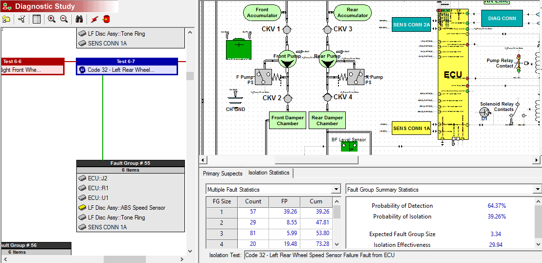
Once the design is initially captured as an eXpress model, computing the Testability of that specific design as well as the impact on that design’s Testability when integrated within a hierarchical design(s) is a core capability in eXpress. We can compute design or the system’s Testability at any “level of replacement” as “Diagnostic Studies” within eXpress. This would then associate the Testability of the system’s design to any functional replacement or “diagnostic level”. This Testability calculation would only be a separate Diagnostic Study from the same design in eXpress. There is no limitations to the number of Diagnostic Studies that can be performed for a design in eXpress.
When performing to operational or maintenance requirements, Testability Analysis should be performed to the level of replacement. The Level of Replacement Analysis (LORA) is an integral activity and requirement of the deployed system or asset.
In eXpress, design hierarchies can be based on the hardware design or simply to represent any diagnostic and maintenance objective, or can be used to do both. Typically, a “system” in eXpress will consist of any number of “lower-level” designs that may support the function of the next “higher level” design. Each design modeled in eXpress only has to concern itself with that particular design as eXpress will automatically generate all of the implied functional dependencies between any objects modeled in that design. This is the simple paradigm that is used to characterize, or “model” the assemblies, subsystems and systems, or even System of Systems (SoS).
So the Testability Assessments in eXpress must first establish the boundaries of the assessment. But be mindful that any model captured in the eXpress modeling paradigm, may need to be assessed in conjunction with any other design(s). This may need to be performed at the same level, any lower level(s) or with any higher level model(s) as required by the testability analysis.
The computation of any operation testability assessment must consider the Fault Detection or Fault Isolation capability metrics for the design as integrated with the other models. This is a very important concept and consideration because FD/FI assessments that are typical in the DFT community, for example, are not typically able to consider any other companion designs external to the boundaries of their technology, LOR, design domain or with integration with externally-developed designs, for example.
Testability across Integrated Design Domains and Hierarchy
The eXpress models provide a robust canvas to include multiple design domains (digital or analog electronic, hydraulic, software, pneumatic, mechanical, optical. etc. or any mixture thereof, and environmental inputs or outputs), and unlimited levels of hierarchy. This is critical because a fielded “system” may have many unknown design-induced constraints that impede or “interfere” with, not just “Fault Detection” at the system level, but also “Fault Isolation” due to such restrictions. The eXpress analysis will, objectively and, sometimes abruptly point out these non-considered diagnostic weaknesses. As a result, the eXpress assessment will educate the analyst on many factors that have unknowingly contributed to over-presumptuous values previously represented in non-eXpress generated Testability assessments.
Capturing the Functional Design
Initially, the functions for each object are represented in the eXpress model. As each object is added and connected by “nets” to any other object, eXpress automatically creates that “functional dependency” or “relationship”. As other objects are connected via these nets, the functional dependencies are fully propagated. When any net misrepresents any logical use, eXpress, upon user action, will check the entire model for logical errors, and provide in depth guidance and assistance for the detailed understanding and the performing of corrected the modeling errors.
It is important to initially capture the functional design as a baseline as early as possible during design development. In this regard, early testability feedback to design development may serve to be timely. There are many more advanced safety and supportability dividends that can be discovered in throughout the design development as discussed throughout the context of this website. But for the purpose of this more fundamental discussion, the performing of early testability analysis simply from the functions captured in the eXpress model, provide an invaluable opportunity to provide a new perspective of the diagnostic integrity and its impact upon the “integrated system”.
Let’s say, for example, failure detection or isolation is unable to support the maintenance philosophy at higher levels of the fielded design. If this shortcoming is discovered early during design development (i.e. before part selection is finalized), then the ability to address this impending and costly sustainment weakness can be worked at minimal development cost, if any. This is a keen place to start using feedback from the eXpress model, if the program is considering risk reduction or “smart” lean development and support objectives.
Capturing and Propagating Failures in the Design
During the process of selecting parts in the development phase, early input from the Reliability engineering can also be captured in the eXpress modeling environment. This is very advantageous because now we can begin to learn which components fail more frequently, are more reliable, and which failures are more critical than others. Combining this ability to “overlay” failure data and their propagation onto the functional design, we have now established a “hybrid diagnostic model” that will produce or integrate with a broad range of functional and failure-based testing assessments, tools and technologies. This melding of failures and functions within a diagnostic model is unique to eXpress and facilitates other advanced operation simulation assessments and run-time capabilities that are also unique to ISDD.
Because there is so many reasons to reuse this data that is captured in the eXpress model, we will be expecting eXpress to establish a database that will generate “turn-key” assessment products as outputs based upon the data detail captured at any time. As the design evolves and matures, the assessments will be able to absorb any new data, reorganize it, and then restructure the data so a full set of new assessment products can be generated with a push of a button. Of course, the assessed data can be “exported” for immediate use in run-time diagnostic environments, so we need to validate the diagnostics to ensure that any tests performed will cover and report the intended objectives.
Evaluating Tests to be used for Deployed Diagnostic Objectives
Once the test coverage is represented in eXpress, we can also accurately determine if the candidate “Points of Tests” are capable of actually obtaining diagnostic status from their “test placement” within the architecture of the design. This is all performed as a core purpose of the “Desktop Fault Insertion” (DFI) feature in eXpress. No other tools can approach this sort of diagnostic validation thoroughness during design development.
The DFI capability enables full design evaluation, which can include any other design(s) contained in the fielded system. It’s best to first use it as another way to validate the test coverage in each eXpress model contained in the integrated system model.
At this point, we’re ready to move on to examining more advanced testability metrics and capabilities that are available and currently being used within eXpress for some of the more sophisticated applications.
Related Links
Calculation of Advanced Metrics for Defense/Aerospace
eXpress Diagnostic Designs And Analysis
Design For Test (DFT) vs. Design For Testability (DFT)
Design for Testability Origin and Evolution
MIL-STD 2165
Related Videos
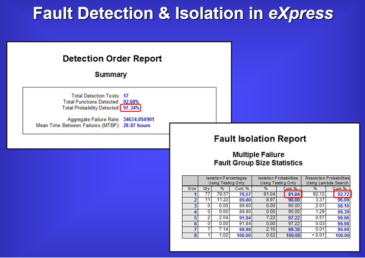
Brief Overview of Testability and Diagnostics Reports
Diagnostic Validation through “Desktop Fault Insertion” (DFI)
