


Solutions
BIT Optimization- Validation – Integration
Traditionally, Built-in-Test (BIT) has been assigned to “test” the presence of the proper functioning at various “testing locations or points”. Such test points have often been selected by the designer or the manufacturer based upon their specific expertise or available resources. If a more careful effort was to be required, then the determining of the BIT would require additional tools, technologies, expertise and then additional resources – meaning more cost and time.
Typically, BIT is designed to solve a requirement at lower levels of the design. This can be performed through a quality checkout of that design piece by exercising as many functions in that design and by validating the proper output of those functions within the context of that design piece.
But what is not always available to the designer or the design partnering activities is that the resources available to objectively assess the “effectiveness” and “sustainment value” of the BIT, not simply for the design piece at hand, but for the inclusion of that design piece into a much larger integrated system.
Higher levels of the diagnostic design will typically utilise the same lower level BIT to form more comprehensive assessments at the higher levels of the system architecture. This becomes tricky because the lower level BIT is spec’d to validate a certain percentage of the functions on their respective design pieces and the next higher levels of the design(s) may not be able to determine which functions are not able to be fully assessed during design development.
How do we really “know” what our BIT is testing?
The short answer is, without the knowledge of the Test Coverage of all of the BIT throughout each design piece within the design, we lack sufficient evidence to prove which functions are being tested and which are not being thoroughly testing at higher levels of the “integrated” design.
Even the most advanced and sophisticated Computer-Aided Design (CAD) tools used TODAY, lack the ability to really incorporate this test coverage specificity at higher levels of the design in many instances. Multiple design pieces designed by multiple design teams using independent design tools and levels of preference and expertise typically begin the clouding of the BIT test coverage as design pieces are integrated. As the collective design pieces spill over into areas where design domains (electronic, mechanical, hydraulic, optic, etc.) begin to cross paths, the BIT test coverage becomes increasingly suspect – to a fault. This is just the beginning of the falling into the No Fault Found (NFF) and Can Not Duplicate (CND) quicksand.
Design for Test (DFT) and Designing for Testability (DFT):
These are two related but separate endeavors. The Design for Test (DFT) and Design for Testability (DFT) processes and objectives are very often confused among experts in the two separate design discipline(s).
Design for Test is typically performed solely for electronic design components (chips, circuit boards, sets of circuit boards) at the lowest levels of design. As a result, Design for Test is inadvertently performed at the expense of the broader vision of the test effectiveness or value at the fielded product (Integrated Systems’ level). Whereas Design for Testability can reuse the investment into Design for Test to validate the test coverage effectiveness at the higher and highest levels of the fielded design.
Evaluating the Test Coverage of the BIT
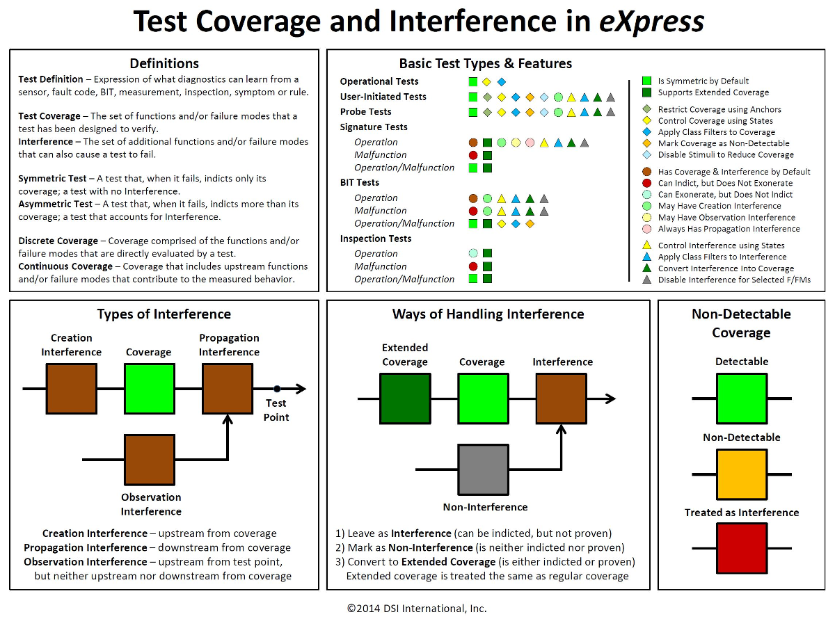
The test coverage is very effectively captured and fully represented in the eXpress modelling paradigm. The test coverage of the BIT is enumerated at any level of the design as is interrogated by the BIT. However, the reporting of the test result by the BIT may have also include any of three (3) types of “Interference”; Creation, Propagation or Observation Interference. Such Interference obfuscates the precision of the test results as reported by the BIT.
Much of the Interference at the higher integrated system levels of the design may not be apparent during the design development lifecycle, nor can it be anticipated by the design team or designer at the lowest levels of the design. Since eXpress forms all of the functional and failure interdependencies throughout the design hierarchy, and hopefully early during design development, any Interference will become quite obvious in the eXpress modeling paradigm as the test coverage is being defined in the model.
Before we can determine the test coverage of any test, we must first choose the proper type of test for any test node. The six (6) “Test Types” used in eXpress are:
- Operational
- User-Initiated
- Probe
- Signature
- BIT
- Inspection
The following chart describes each of the six (6) Test Types in eXpress as well as the three (3) types of “Interference” that affect the test coverage of those tests. But most importantly, the chart shows how the tests types and the Interference are easily managed in eXpress:
Diagnostic Validation
Traditionally, designs have been developed with little attention to discovering the design’s diagnostic integrity. Engineers are overwhelmed with many tasks while Program Management hasn’t really understood the widespread value of diagnostic engineering.
Designing for Test (DFT), Health Management (PHM, ISHM, etc.) or multiple sustainment levels, is a more complex task today. It ultimately embodies a more integrated systems’ understanding of the “Test Coverage” sophistication when considering the incorporation of many designs across a complex hierarchical design architecture.
Likewise, Designing for Test on medium to complex CCU’s, such traditional DFT or any independent Test Coverage analysis fails to provide Diagnostic conclusions – at any level or in consideration of the fully fielded product application. . Once integrated with other designs and fielded, any test results obtained for use with any on-board BIT or for any continued, secondary level (Depot or ground maintenance) will be dependent on the diagnostics integrity of the “integrated systems’ design – regardless of the “test coverage” specs described in the static DFT analysis.
This is where we experience and rely on the “Diagnostic Integrity” of our design(s). The diagnostic integrity is dependent on the design domain mix involved, its complexity and the ability to evolve as the operational environment or implementation changes. Fortunately, DSI Diagnostic Validation capability using the DFI feature in eXpress has no difficulty in considering all of these complexities to exhaustively determine the diagnostic effectiveness of any complex or large-scale (integrated systems’) design(s).
Validating the BIT Test Coverage and Create/Assign Fault Groups to the BIT
After the BIT is fully validated (using the advanced eXpress Diagnostic Validation, or Diagnostic Fault Insertion capability), the integrated designs will be capable of performing to the diagnostic precision at any level(s) of the diagnostic design hierarchy as validated in eXpress.
The following two (2) images show a sneak peek at the robust eXpress “DFI” capability:
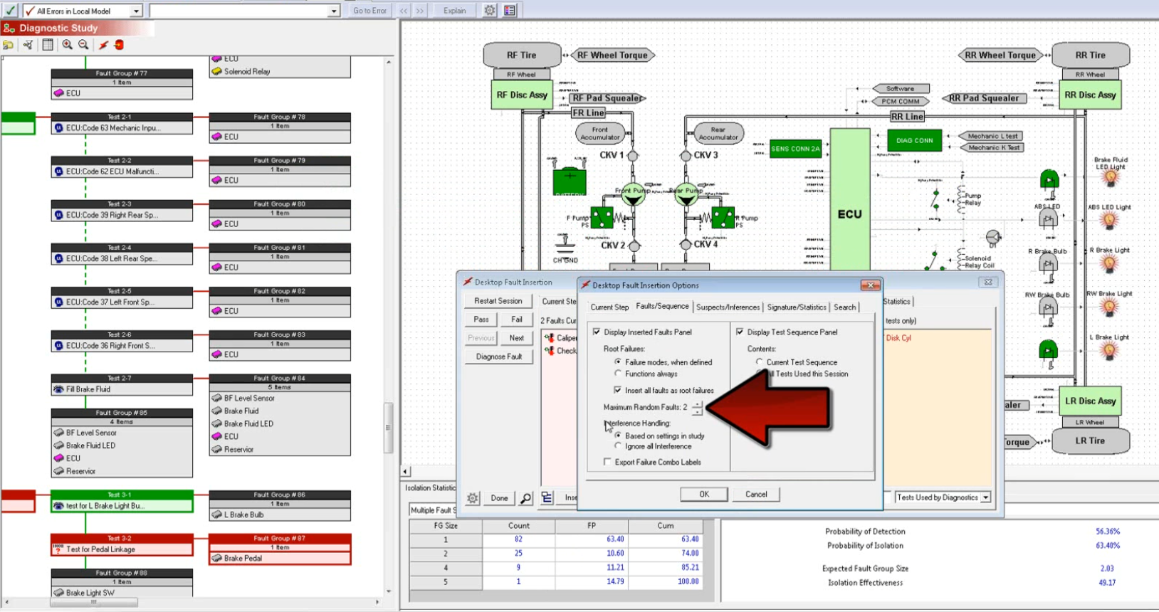
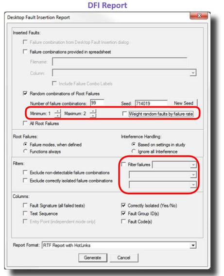
The image below shows one of many settings dialogs from the “DFI” capability:
In the image above, the eXpress DFI feature allows the user to fully trace the entire path and/or diagnostic inferences produced across all hierarchical levels of the diagnostic design architecture. This is how the full impact of the Test Coverage is observed both from a diagnostic sequencing perspective (diagnostic tree on the left) and the comprehensive visual perspective using the design window on the right.
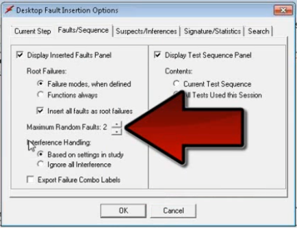
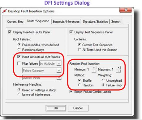
This eXpress DFI Diagnostic Validation capability allows the filtering of inserted faults by severity (so that only failure modes that propagate to an end effect of a certain minimum severity are inserted) or by attribute (so that only failure modes with a given attribute value are inserted). This feature—which impacts both explicit faults selection and randomly-generated faults—allows you to focus diagnostic validation efforts on more critical failures, or failures of a certain type.
By default, random fault insertion works in “shuffle” mode, which prevents faults from being inserted more than once until all other faults have been inserted.
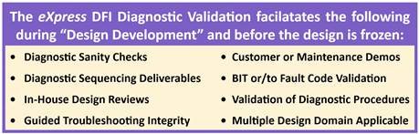
While there are an infinite number of uses and benefits from the ability to validate that diagnostic quality of any design, or collection of integrated designs, the most valuable impact can be gained during design development characteristic is to enable an opportunity to facilitate the maximum
The image above shows the versatility of allowing the user to generate reports that can be pushed off to a spreadsheet and then enable an interoperable capability to reimport from the spreadsheet to seed future diagnostic sessions as configured for any demo or any other purposes!
There are many uses of the selection of DFI Reports so that a comprehensive report can track the capability of any set or all sets of any inserted faults. This is a unique and interactive capability that can only be found within eXpress and DSI’s ISDD !
Fault Code Assignment, Integration & Management
Within the eXpress and Integrated Systems Diagnostic Design (ISDD) environment, the assigning and managing of the Fault Codes for the BIT throughout the design development of the Integrated Vehicle Health Management (IVHM) is a rather simple and error-free integrated process. To perform this seamless capability for any IVHM or Integrated System Health Management (ISHM) implementation, the ancillary eXpress Maintenance Module is required. The approach described below highlights some of the procedural steps to prepare the eXpress model for this additional purpose and benefit.
Maintenance Module Interoperability
The eXpress Maintenance Module is an advanced capability that leverages the vetted BIT test coverage described within eXpress and prepares it for use in operational and sustainment environment(s). As the demand in industry continues to expand for this technology, the eXpress Maintenance Module will continue to evolve to accommodate a myriad of advanced run-time diagnostic requirements.
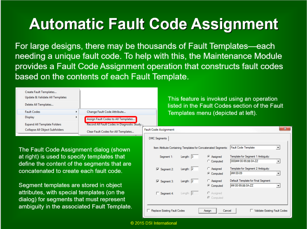
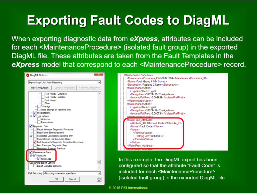
Auto-Assign the Fault Codes:
Once the BIT has been fully validated throughout the diagnostic design hierarchy, the Fault Codes can be “auto-assigned” to each Fault Group, or to whatever sustainment paradigm is deemed appropriate for the project. Refer to the two (2) images below that describe the Assignment of the Fault Codes and then exported to the sustainment paradigm.
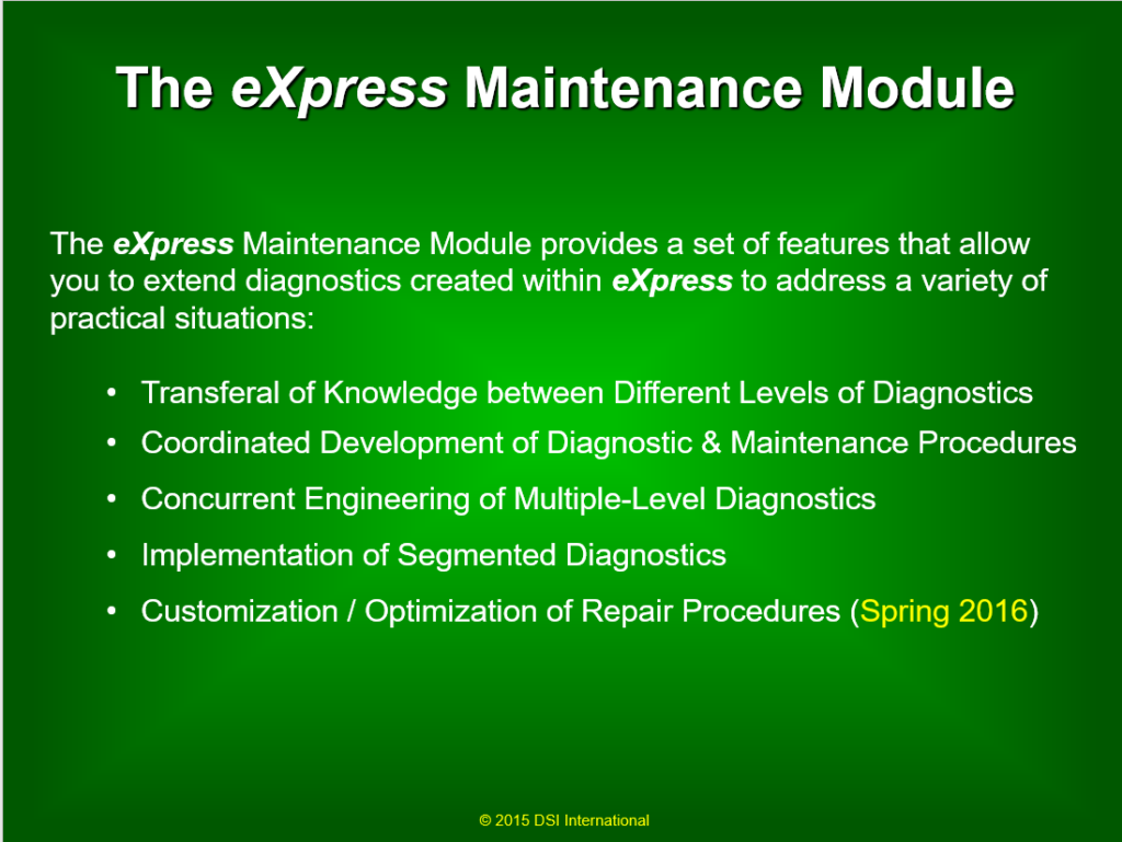
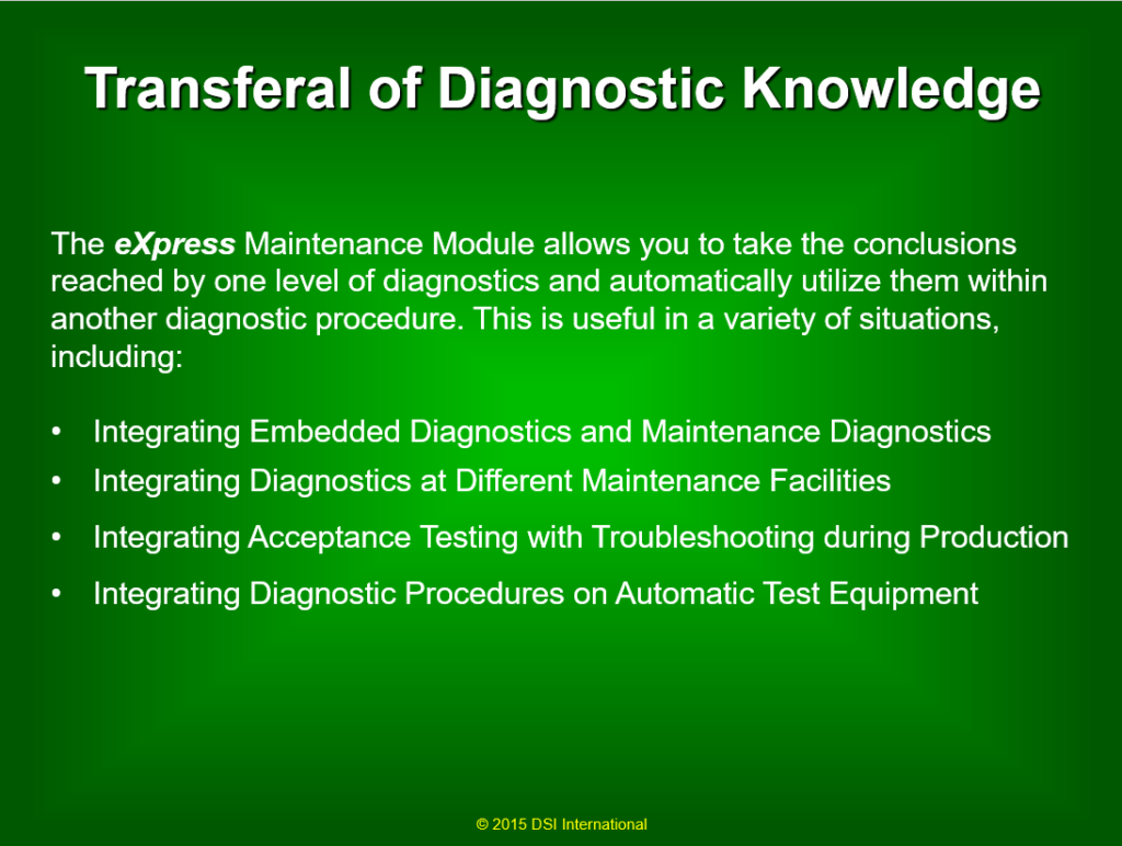
Transferal of Diagnostic or BIT Test Coverage Knowledge to the Operational Environment
At this point, we simply transfer this knowledge to the field. This can be performed for an array of implementations as described in the following image.
Related Articles and Presentations:
Optimized Sensor Placement Strategies in eXpress to Reduce False Alarms
Boundary Scan in eXpress
The eXpress Maintenance Module
Test Types in eXpress
Related Videos:
BIT to Guided Troubleshooting
Diagnostic Validation Through Fault Insertion
COTS-Based Solution for Through-Life Support
