


Solutions
Designing for IVHM or any On-Board Health Management
The eXpress diagnostic modeling environment is essential for determining the diagnostic designs’ ability to “Uniquely Isolate” any failures (or loss of function). This capability, designated as “FUI” in eXpress, enables the assessment to determine if the design is able to isolate between the sensor and any of the functions contained on the object that is being sensed.
The Value of “FUI” inherent to eXpress
More specifically, this design development life-cycle assessment capability identifies if any (on-board, BIT reported, for example) functional failure is able to be discerned between the loss of any other specific “unique” function (contained within the same failure space), as based upon the ability for the sensors to sense between those functions (at any particular operational state) and given the diagnostic integrity of the sensor(s) at the time of the interrogation. This is a critical capability since this is where False Alarms and False System Aborts (FSA) are rapidly introduced. In lieu of writing about countless examples to substantiate this critical point, it would be much simpler to review the design’s impact on these sort of metrics in an interactive operational support simulation-based environment.
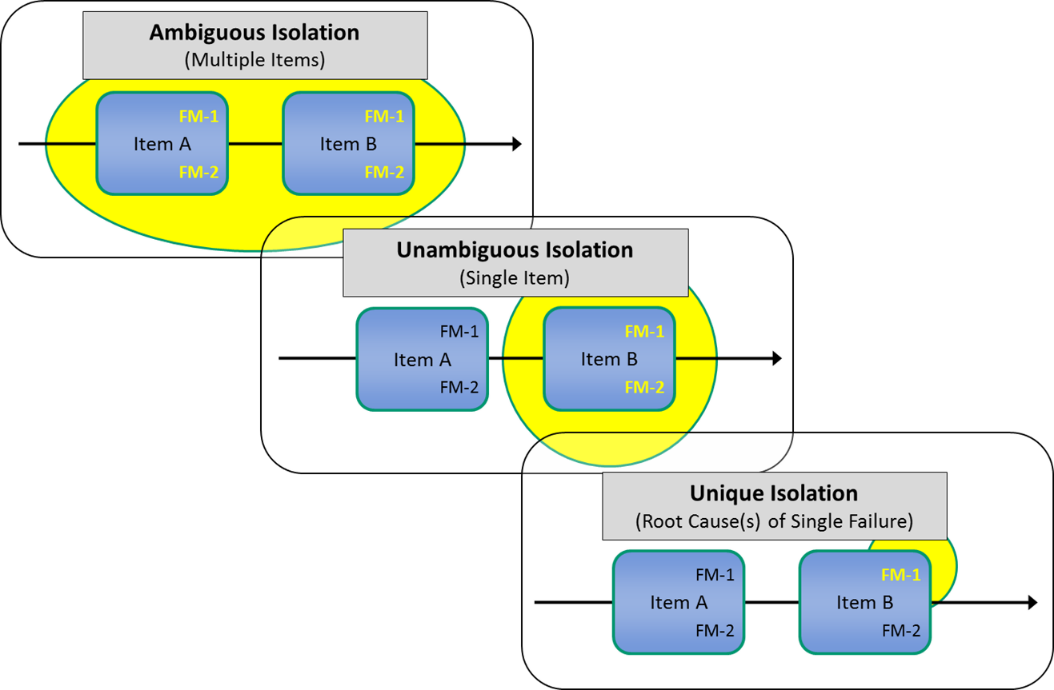
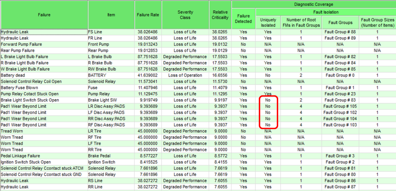
One of the turnkey eXpress FMECA Plus configurations is the “eXpress Critical Diagnosis Chart,” is shown above. It allows the viewer to examine a “Uniquely Isolated” column indicating whether the fault group that is isolated for this failure contains only root causes of the given failure. If the fault group contains any failure modes that are not a root cause of that failure, then the failure has not been uniquely isolated by the diagnostics. The non-unique isolation of critical failures is a primary driver of false alarms and unnecessary system or mission aborts.
The ISDD process, through the eXpress diagnostic modeling environment, is able to output an eXpress diagnostic design data file that is directly importable to a fully integrated sustainment simulation companion tool, or “STAGE”. The captured diagnostic design data used to produce assessments (FD/FI, FMECA’s and many other required assessment products) is used directly in STAGE to seed time-based sustainment metrics. From the STAGE simulation, such stochastic values as calculated for FA, FSA, MTBCF, MTBSA, MTBUM, RUL and well over 200 additional (and ground-breaking) sustainment-related graphs are produced. “STAGE” provides a pallet for the assessing of virtually an unlimited assortment of operational support and Health Management simulation calculations. With respect to the IVHM or any design, the STAGE simulation is able to simulate the occurrence of failures of components (and based upon their respective diagnostic design impact) in accordance with their assigned failure rates over a selected sustainment horizon (“lifetime”). In this manner, the designs’ inherent diagnostic architecture becomes exposed. Below is an example of the impact of FUI in a graph showing the System/Mission Aborts in STAGE:
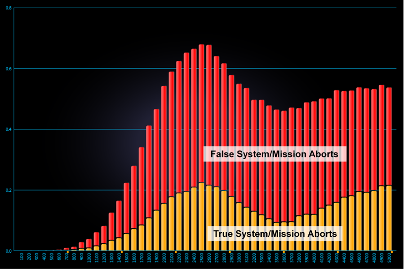
An additional capability of the STAGE operational support simulation is that the calculations consider the impact of maintenance activities. In this manner, the results computed by STAGE reflect the value or costs associated with any proposed sustainment philosophy. When the diagnostic design is augmented with any selection of sustainment “mixtures” of preventative and corrective maintenance, STAGE will consider these parameters when producing the selected simulation graphs. These graph(s) produced from the STAGE simulation show the strengths and weaknesses of the integrated systems’ diagnostic design in a broad range of critical assessment graphs along with any selected interrelated costing or performance-related graphs. All of the STAGE graphs can be immediately exported to MS PowerPoint while the data contained in the graphs can be, likewise exported to MS Excel, which facilitates ease of data sharing. This is just another immediately available design & support assessment collaboration option requiring no additional data input.
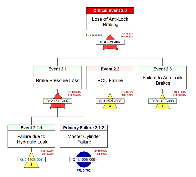
As mentioned earlier in this paper, any capturing of the diagnostics design within the eXpress modeling paradigm, the designs’ functional and/or failure effect propagation interrelationships are able to be captured in a single representation. Due to this unique eXpress diagnostic design capturing paradigm, the same “eXpressdiagnostic model” can be used for evaluations of a design’s diagnostic capability in ground-breaking and unmatched perspectives and detail. The eXpress models can also behave as “building blocks” that can be immediately used in the creation of hierarchical FMECAs, FTAs, prediction of diagnostic performance, and generation of assessment-to-actual runtime diagnostics. Supporting these capabilities, the eXpress modeling paradigm includes the generation of a wide variety diagnostic-output(s), XML compatible run-time diagnostic file outputs, and implementation(s) targeting evolving sustainment technologies. Below is an example of the impact of FUI in a turnkey FTA output from eXpress:
While forcing continued traceability to the diagnostic designs’ maturation in both the development and the sustainment life-cycles, eXpress models may be initiated during any phase of the design development process, but offers increased value and opportunity when instituted as early as possible in the design development life-cycle. Accordingly, the eXpress models can be used or modified as needed, to perform iterative and “current” assessments of the diagnostic capability of the (integrated) systems’ diagnostics design, thereby providing useful design feedback to FMECA analysis within the RCM Process to better substantiate any advance diagnostic implementation in the sustainment paradigm, including CBM+.
Combining Talent: eXpress and IVHM Design
In conjunction with the advanced eXpress Diagnostic Modeling capability, the host embedded on-board IVHM application is able to provide an efficient framework for organizing salient knowledge acquired from the subsystem or selected system(s) under analysis. The diagnostic reasoning activities are ultimately capable of achieving consistency with the diagnostically-optimized IVHM capability from the process of being vetted in the eXpress diagnostic modeling paradigm. In this manner, any BIT failures (and “Diagnostic Conclusions based thereon) retrieved by the on-board IVHM application are able to be “bridged” to the off-board sustainment paradigm.
Contemporaneously, and while the IVHM performs its function on-board the vehicle, any BIT data retrieved in the off-board sustainment environment can be diagnostically interpreted in a more comprehensive and diagnostically-conclusive manner. This is the result of influencing the diagnostic designing of the on-board IVHM to, and, for the “bridging” of the diagnostic designs’ BIT data to more effectively commence the off-board second level sustainment activities.
The difficulty in creating an IVHM diagnostic system lies in designing of a diagnostically-savvy knowledgebase for the physical system because of inevitable tradeoffs between complexity and completeness. Of course, this must begin by first establishing of the “diagnostic integrity baseline” of the “Health Management Reasoning” and its role as an integral component of the broader, more inclusive, on-board IVHM architecture. “Cost-benefit” tradeoffs are effectively attained within the eXpress modeling paradigm, given a collaborative and cooperative working environment with equally shared vision and objectives.
Systems’ Integrators have the option to leverage the captured eXpress diagnostic design models in the generation of “eXpress output FMECAs”, capable of cross-validating the data contained therein with the designs’ Fault Tree Analysis (“FTA”), and visa-versa. This ability to “toggle” from, or back to, the eXpress FMECA and the eXpress FTA, which is essentially, the diagnostic designs’ “turn-key” automated, “top-down” view of the FMECA. The initial top-down representation of the eXpress FTA, can be referred to as the “Inverse FMECA”, meaning that it provides an architectural platform to instantly account for the inclusion and propagation of all Primary Failures contained in our targeted FMECA and their interrelated combining failure effects, as they propagate to the top level of the design or system.
The eXpress FTA is another assessment product output of the eXpress modeling paradigm, which is traceable to the diagnostics design of the (evolving) integrated system. The eXpress modeling paradigm is able to (re)use existing data or mimic earlier created FTA output representations from FTA’s created in a separate tool, method, or by a third party supplier, which are traditionally created in a manner that is separate and adjunct to the designs’ diagnostic designs’ architecture. Traditionally, FTAs have not been concerned with the integrated systems diagnostics design architecture, which is an ongoing costly weakness of that traditional approach. Some of the costs will be expressed and/or implied within this paper and some of those ongoing costs become more painfully apparent when the burden is shouldered by those without “a dog in the fight”.
The natural path forward is for the Systems’ Integrator is to produce the FTAs for or within their company-required tools or methods. But since the Systems’ Integrator is a “systems integrator”, it will be also need to remain open to receiving FTAs produced by other suppliers in other methods and tools – and there’s a likelihood that some those major subsystem suppliers may have produced, or intend to produce eXpress models. In this regard, the eXpress modeling environment allows for Systems’ Integrators to have it both ways.
Regardless if the traditionally produced FTAs were generated internally by the Systems’ Integrator, by any external third party, or may otherwise exclude costly design updates into existing FTAs, the establishing of the eXpress FTA provides an innovative alternative to such traditionally-rigid FTAs. The eXpress FTA gracefully extends the utility and ease of (re)producing and maintaining an evolving, uniform “integrated systems” eXpress FTA. This enables the eXpress FTA to seamlessly and continuously reflect design updates or the occurrences of maintenance activities throughout the sustainment life-cycle
Maintenance activities forever change the ensuing failure characteristics of the integrated system. To this point, a stern position of FTA “agility” is itself, a risk avoidance measure.
This eXpress FTA allows for the immediate top-down visualization of the design level effects of the primary failures contained in the selected level of analysis as identified in the companion FMECA design(s). Meaning, if the FMECA is targeting the FTA to include the component or box level failures as primary failures, then the level of the FTA analysis can support either alternative, or as limited by the level of FMECA data available
The eXpress FTA enables the interactive inclusion of “and” gates and polling “or” (“K of N”) gates, external events and a host of other symbols typically used to represent more complex interdependent failure events. A host of other fundamental capabilities are also characterized within the eXpress FTA to maintain a sense of familiarity with more experienced folks delving in this aspect of the Reliability Engineering discipline. Some of those typical visual hallmarks include the “probability of occurrence” or “Q” calculation for any “cut set” contained within the eXpress FMECA, and thereby inference, the integrated eXpress FTA.
Where the separations begin to occur when describing the diagnostically-influenced FTA from the adjunct traditional FTAs, is that the eXpress FTA is cross-validated with the FMECA and the diagnostic capability of the design interrelated therewith, which opens the headroom for enriched “diagnostically-savvy” FMECAs and FTAs. This is a discriminating capability because, not only are all of these assessment products capable of being updated instantly, consistently and comprehensively, but so is “true-to-form” with respect to the companion (evolving) diagnostic implementation(s).
In briefly highlighting an advanced capability that becomes part and parcel within the eXpress FTA assessment product, is the ability to discern which percentages of the condition (calculation) leading to the undesirable event are able to be “uniquely isolated” in that specific “branch” or “cut set” representing the occurrence of that undesired event. This enables uniquely valuable “inside” information that, from an integrated systems design development or sustainment perspective, is able to determine the portion, if any, of the undesired event is able to be detected or isolated as determined within the constraints of the test coverage of the BIT for and by, any particular operational state, for example. The eXpress FTA also enables the inclusion of “Prognostic Events” to be fully integrated and included in the calculation of the probability of occurrence of undesired events, given prognostics.
As a result, the companion eXpress FTA baseline architecture is automatically generated once the integrated systems and the FMECAs are fully captured in the eXpress models. This is performed early in the design development life-cycle, which will greatly enrich and support the IVHM design development paradigm. By capturing all interrelationships and interdependencies subsystems’ functional and failure effect propagation, eXpress (and its companion ISDD tool suite) influence the IVHM design the opportunity to take advantage of robust and agile diagnostic alternatives that are not technologically or cost-effectively possible for traditional IVHM designs.
The most obvious sustainment value begins with the eXpress Diagnostic Models as they are also (re)used to support the production or maintenance environment(s). In this implantation, the captured diagnostic design will instantly improve the accuracy and effectiveness of maintenance tasks via any compatible technology or Portable Maintenance Device (PMD).
But additionally, the importing the eXpress diagnostic models into its companion Run-Time Guided Troubleshooting Application adds another level of advanced diagnostic continuity and capability.
This Guided Troubleshooting Application can be hosted or accessed via a fully-featured API. This provides the maintainer with the ease of access to any preferred GUI without losing the benefit of the eXpress diagnostic design knowledgebase. This flexibility is greatly enhanced while the guided troubleshooting performance on the PMD is largely improved.
Please double-click the link to see an actual demonstration: BIT to Guided Troubleshooting
Since traditional on-board IVHM implementations have lacked the need or ability to determine any knowledge of “fault isolation groups” from the retrieval of triggered on-board BIT failure codes, the “bridging” of the diagnostic conclusions able to be gained from the on-board assessment(s) are essentially not existent. Again this is a typical (costly) shortcoming of traditional on-board to off-board sustainment approaches.
This shortcoming goes typically undisclosed or ignored when the opportunity to redirect or open up the solution options is not a timely or favorable endeavor. Accordingly, the ending sustainment capability suffers unnecessarily from such traditional IVHM development practices.
That said however, and when the off-board diagnostic sustainment paradigm is able to derive diagnostic conclusions, due to its inclusion in the design development of the IVHM and any related BIT codes, it will enable the off-board diagnostic solution to “bridge” the sustainment implementation(s). This integrated and “bridged” sustainment implementation will allow for more intelligent back-end diagnostic implementations to be instantly serviceable. Going forward, it’s easily adaptable to technology evolution. This evades the inevitability of on-board IVHM from being a mostly rigid and costly implementation to update for bridging to off-board diagnostic paradigms in the future. Going further and as failure resolution is gained from the off-board guided troubleshooting paradigm, the history of these resolutions is captured in any robust or commercially available database tool structure.
As the maintainer steps through the off-board guided troubleshooting experience in this “BIT to Guided Troubleshooting” demonstration, any prior failure resolutions are able to be accessed contemporaneously with the UUT design knowledge. This is another unique quality that allows the maintainer to be guided by empirical knowledge (past diagnostic resolution given current diagnostic status), but also provides the design knowledge to the maintainer. In this regard, the maintainer isn’t going to be surprised by First Failures (cons of case-based reasoning) and the maintainer can leverage past experience (pro of case-based reasoning). But going forward, this new off-board paradigm will also enable the inclusion of prior or existing fault resolution data from legacy systems. This enables its use to benefit from being included early in deciding sustainment alternatives and also facilitates a gateway to add new value to existing legacy paradigms where sustainment costs have already exceeded their welcome.
Systems’ Integrator has the opportunity to greatly enrich and define its sustainment capability and value for the future. We shared some of the highlights of a truly unified and integrated systems diagnostics design paradigm. To this purpose, the sustainment capability should always be considered an equal priority in the “designing for influencing sustainment” in the “designing development” life-cycle – but in a much more cross-disciplinary-boundary environment. It must not be deterred with distractions or the narrowness of objections as only the sustainment implementation activities burden the scars from belated or complacency-natured decisions – from theretofore.
