


Solutions
Incorporate Multiple Technologies into a Single System Assessment
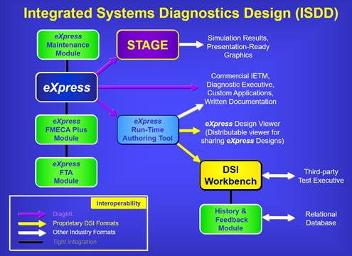
Introducing “ISDD” to the Systems’ Integrator
Many of the ideas and concepts regarding the targeting of an “agile” maintenance strategy for System or the System of Systems (SoS) begin with the formalizing of a unified approach to collectively capture the functionality of the participating designs into a robust integrated systems’ design development and process. But this design development process must be able to fully assess not solely the top-down functional allocation Systems’ Design and Sustainment Requirements (Operational Availability, etc.) but also be fully positioned to assess and validate the functional and failure cause (root cause) propagation from the bottom-up.
Integrate Lower-Level Subsystem Designs
Designing for the System or Vehicle sustainment lifecycle must consider the adopting of a well-planned diagnostics engineering process using that facilitates a multi-organizational approach to advanced and robust tools that do far more than simply “share data”. However, initially, the sharing of diagnostically-relevant design data should be sufficiently robust to be performed between design disciplines (e.g. Reliability, Maintenance or Diagnostics Engineering) and partnering companies and while seamlessly crossing design domains – effectively and comprehensively. This “shared” data will be restructured in a collaborate environment and then fully integrated by Systems Integrator.
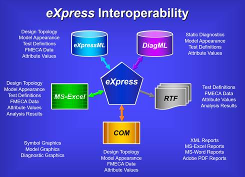
The diagram above depicts the various forms of data that can be imported or exported from eXpress
Importing Data from Spreadsheets
There are different ways that data can be imported into eXpress from Microsoft Excel spreadsheets.
Of all the different methods of automatically bringing external data into an eXpress model, the most frequently used are the various Microsoft Excel spreadsheet imports. This is due primarily to the widespread practice of using Excel worksheets as either repositories of project data, or as a preferred format for representing information that must be shared by different engineering efforts.
eXpress allows a wide variety of data to be imported from spreadsheets:
- First of all, you can import the topology of the design. Depending upon what data you have available, this can range from simple connectivity to detailed functional definitions.
- You can also import the placement and appearance of the various elements in the model.
- Attributes values are frequently imported into eXpress from spreadsheets. Attributes are project-specific values or text that can be associated with any of the basic elements in a model. Commonly imported attributes include item failure rates, part numbers, circuit IDs and Logistics Control Numbers.
- One of the most common data sources are Reliability spreadsheets. Initially the result of a failure modes and effects analysis, these spreadsheets are often enhanced with other failure-related information. You can import not only failure rates and other attributes, but also the individual failure modes, failure effects and severities.
- Project spreadsheets sometimes contain information that can help automate the test definition process. If, for instance, a Reliability spreadsheet includes a column listing the BIT associated with each failure, you can import these BIT definitions into eXpress.
- A variety of other data can also be imported from spreadsheets, including static test sequences, user-defined inferences to be applied during diagnostics, lists of faults for the Desktop Fault Insertion capability, and events
used by the Fault Tree Analysis module.
Many of these different import capabilities are demonstrated in videos in the “Importing Data from Spreadsheets” series. This series of videos begins with an initial demonstration of the design Topology Import. The use of this import enables the rapid construction of a basic model from elements in an Excel spreadsheet.
Combining Multiple Technologies and Design Domains
Once the diagnostic data sharing paradigm has been instituted, ISDD establishes an enriched integrated diagnostic design development environment that, while protecting the sensitivity and proprieties of any externally-supplied design data, enables a comprehensive and agile data integration mechanism for the System Integrator to “integrate” and “repurpose” the shared data into the System, regardless of design size, complexity or mixture of Design Domains:
- Digital/Electronic Components (Circuit Boards, etc.)
- Mechanical/Electrical Systems
- Hydraulic/Pneumatic Systems
- Software Inputs to Designs
Concurrent Engineering or “Scalable” Design Development
The ISDD design development process fosters the diagnostic integration of both interim and final development deliveries of the design’s related diagnostic engineering data. The diagnostic engineering data will minimally include the determining of the most optimum test placement of sensors, BIT or test observability, if any, by the describing of the test coverage per each test per any operational mode or condition of the design as a function of the operational System.
The comprehensiveness of the diagnostic data results from the implementation of the ISDD process, which permeates through traditional design discipline boundaries. As the diagnostic design data is provided by any companion design discipline or external team partner, ISDD establishes a structure that produces an evolving and “living” diagnostic model as it integrates each design piece throughout the design development lifecycle.
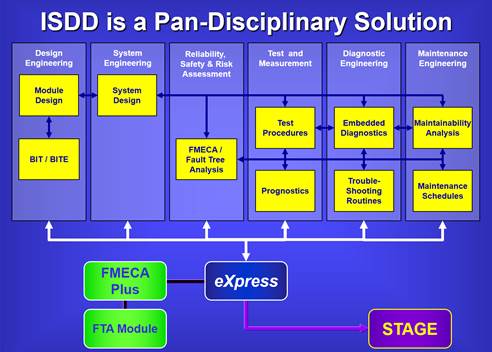
The chart above depicts the general responsibilities of each design discipline during the Design Development Lifecycle
Assessing the progress of the diagnostic capability of any developing piece or combination pieces of the design can be assessed at any time throughout the diagnostic development process. Therefore, at any point during development any progress towards the diagnostic requirements can be tracked, modified or enhanced as the design progresses. Design decisions (parts selection process, test point selection, maintenance philosophy, diagnostic reasoning technologies, etc.) can also be evaluated against the System sustainment requirements (Operational Success, Mean Time Between Operational Aborts, Operational Availability, etc.). This can be worked and levied against all levels of the design and at any desired point during design development as the assessments should be retrieved upon demand as “outputs” from the captured diagnostic design(s).
Determining the Diagnostic Integrity of the Design
The Diagnostic Integrity of the design is the determination of the maximum diagnostic capabilities, and any related constraints learned from the assessing of the Fault Detection and Fault Isolation expectations of the design in any operational or deployed paradigm. Typically, expressed as “FD/FI”, or “FDI”, as an integral component of a Testability Assessment, expose the strengths and weaknesses of the diagnostic capability of the design sufficiently early during design development lifecycle that any feedback from the “Testability Analysis” can better influence the design for a more cost effective sustainment lifecycle.
Related Links:
BIT Optimization – Validation- Integration
Facilitating all levels of Design Architecture
