


Support
Boundary Scan modeling in eXpress
David Cole
MBDA (UK)
COPYRIGHT NOTICE
This document, which is supplied in confidence, is the copyright property of MBDA (UK) Limited. Neither the whole, nor any extract may be disclosed, loaned, copied or used for any purpose other than those purposes for which written permission was given at the time of release. Application for any lifting or relaxation of these restrictions must be made in writing to MBDA (UK)Limited, who may in their sole discretion refuse such application or give it qualified or absolute approval.
The information in this document may also be subject to a National Security grading in accordance with the Official Secrets Act 1911-1989.
MBDA (UK)Limited
All rights reserved ã 2006.
1 INTRODUCTION
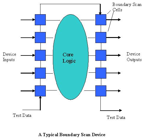
1.1 Boundary Scan device types are now finding their way into many product designs. The use of Boundary Scan testing offers many advantages for Manufacturing Test, specifically as a high-speed test technique for component interconnects, as well as offering good diagnostics.
1.2 A fast and effective method of modeling System Boundary Scan using the eXpress Testability Analysis Tool has been developed. Testability questions surrounding the inclusion of Boundary Scan in a system design, specifically Functional Coverage (what is / is not tested) and Diagnostics, can now be addressed using the eXpress modeling tool.
1.3 The information from the eXpress analysis can now be fed back to the System Test Development Team to help understand what additional testing, over and above that covered by Boundary Scan, is necessary to provide adequate System Functional Coverage.
1.4 The innovation in this technique lies in the ability to make use of Device State Switching in eXpress to change (by simply throwing a switch) between the required Boundary Scan operational modes. The technique of creating and connecting the Boundary Scan Cells also lends itself to use of fast auto replicate methods, ensuring minimal effort in converting an existing eXpress model device into a Boundary Scan version.
Click here to view larger image
2 DETAILED IMPLEMENTATION
2.1 As described above, this method incorporates the addition of discrete Boundary Scan cells to a modeled device, and uses a lower level of hierarchy in which to perform the addition. It has been necessary to make the input cells slightly different from the output cells so they can cater for the required boundary scan test conditions. Once created, the cells may be copied and pasted as many times as required to cover all device inputs and outputs.
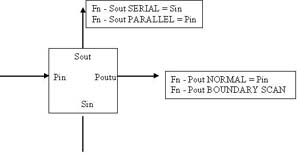
2.2 Definition of an Input Cell in eXpress
Click here to view larger image
2.2.1 STATES
PARALLEL SERIAL = Fn – Pout BOUNDARY SCAN
Fn – Sout PARALLEL
Fn – Sout SERIAL
SERIAL = Fn – Sout SERIAL
INTEST = Fn – Pout BOUNDARY SCAN
Fn – Sout SERIAL
NORMAL = Fn – Pout NORMAL
In order to minimize problems during Design State creation, do not make ‘Mutually Exclusive’. Allow ‘No State Selections’.
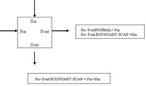
2.3 Definition of an Output Cell in eXpress
Click here to view larger image
2.3.1 STATES
NORMAL = Fn – Pout NORMAL
PARALLEL SERIAL = Fn – Pout BOUNDARY SCAN
Fn – Sout BOUNDARY SCAN
SERIAL = Fn – Sout BOUNDARY SCAN
In order to minimize problems during Design State creation, do not make ‘Mutually Exclusive’. Allow ‘No State Selections’.
2.4 Operations for a Boundary Scan Cell
The various operations of a Boundary Scan Device can now be defined by selecting an operating State for Input Cells and Output Cells as follows:
Note: It is also necessary to create an ON State for the Device Logic to enable it to be switched On and Off.
Normal Operation
Input Cells = NORMAL
Output Cells = NORMAL
Device = ON
Clock Data From TDI to an Output
Input Cells = SERIAL
Output Cells = PARALLEL SERIAL
Device = OFF
Clock Data from TDI + Inputs to TDO (EXTEST)
Inputs Cells = PARALLEL SERIAL
Output Cells = SERIAL
Device = OFF
Clock Data from TDI Though Device to TDO (INTEST)
Input Cells = INTEST
Output Cells = SERIAL
Device = ON
2.4.1 The above State settings are used to define a set of Design States that are then used to set the operational condition of the device at the next hierarchical level up from where the Boundary Scan cells are defined. Hence, for Normal Operation, all cells will have been set to NORMAL when defining the required Design State. This greatly simplifies the way the device conditions can be changed from one mode to another, rather than always having to set the state of each Boundary Scan cell.
Make top-level Design States ‘Mutually Exclusive’; (Default).
2.5 Implementation
2.5.1 eXpress version 5.10.3 has new features that make the application of this Boundary Scan technique into a system design very fast and straightforward. It is now possible to replicate objects and do it in such a way that they automatically are placed in a vertical column. It is also possible to automatically connect all the net connections to the Boundary Scan cells:
2.5.2 Start with an object with correctly named ports.
2.5.3 Copy the object into a new design. This will be used as the lower level model for the device, hence where the Boundary Scan Cells will be placed.
2.5.4 Move all the input ports of the device to the left hand side and the output ports to the right hand side using auto move option.
2.5.5 Next, auto create the required I/O flags (to represent the upper level ports) by first selecting all ports and then, using right click to invoke the Auto-Connect feature; ‘Create I/O flags and Connect to Selected Ports’. Set the net naming method to ‘Use Port Abbreviations’.
2.5.6 Once the I/O flags are created, disconnect them from the device and move them further away to allow space for the Boundary Scan Cells.
2.5.7 Copy and Paste an input and output cell from a working example, or from a user library (just one cell of each type). Then use the eXpress ‘Replicate Object’ feature to copy as many as required (one per port) down each side of the logic device.
2.5.8 Next, select all ports and, then invoke the Auto Connect feature. Use the ‘Select Ports on Adjacent Objects’ with the Priority set to ‘Objects with Most Ports’ and click the ‘Allow One to Many’ check box. This will connect up all of the required nets except for the top scan chain connection and TDI and TDO connections which have to be done manually.
Note: Object alignment (in the vertical) has to be perfect for this to work correctly, which is why using the Replicate Object utility works well. Alignment can also be achieved by using the ‘Align or Distribute’ option and selecting the ‘Distribute Vertically’, and ‘Align Center’ commands. The ‘Distribute Vertically’ command is especially useful, as once both the top and bottom Boundary Scan cells are placed to line up with the top and bottom object ports respectively, all the other cells between these will be distributed the correct distance apart. The ‘Align Center’ command ensures all cells are aligned in the vertical axis.
2.5.9 Create the Design States for the required Boundary Scan operational modes as previously described by selecting the required Boundary Scan states for both input and output cells. These Design States are then visible when selecting the required Boundary Scan mode of operation for each test within an eXpress Test Set.
2.6 Using Boundary Scan Devices Within An eXpress Model
2.6.1 Once created, Boundary Scan devices can be setup to simulate the various test modes available from this technology. For example, if two or more Boundary Scan devices are present in a design, and there is an area of Non-Boundary Scan circuitry in the circuit path between them, (known as a Cluster), then it may be possible to drive the output(s) of one Boundary Scan device (using TDI) so that a signal is sent out, via the Cluster, and into an input of a second Boundary Scan device set to receive on its inputs and output on TDO.
2.6.2 Hence, by controlling the modes of operation of each Boundary Scan Device, as set by selecting the required Boundary Scan Design States within each eXpress test, the full capability of Boundary Scan testing can be modeled.
2.6.3 It is also possible to determine the benefit of performing INTEST (testing device internal logic). Differing failure rates can be set between the Logic block and the Boundary Scan Cells (within the lower level model of a Boundary Scan device), thus revealing a level of coverage (when only EXTEST is performed) that does not include the internal logic, but may, nevertheless, cover what is often felt to be the most unreliable area of the device; the I/O pins (and associated tracking / soldering).
3 CONCLUSION
There are numerous ways in which Boundary Scan technology can be modeled in the eXpress Testability Analysis software tool. The technique described here makes use of a number of power features incorporated into the latest eXpress software to provide a fast, effective and adaptable means of modeling Boundary Scan technology, and can be easily incorporated into either new or existing model designs.
